


24 - 1
REPLACEMENT AND CLEANING OF PHOTOMETRIC COMPONENTS
ETC00781(4) Series 100 e 02/2004
24. Replacement and Cleaning of Photometric Components
24.1 Taking out the Photometer Assembly
P Open the analyzer housing (cf. chapter 23).
P Disconnect all electrical connections between photometer assembly and electronic unit
and disconnect all gas lines from the photometer assembly.
P Only analyzers with gas detector:
Remove preamplifier (Fig. 3-2, Item 5) from holding device (Fig. 3-2, Item 4).
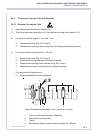
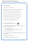
P Remove the two screws shown in Fig. 24-1 as Item 1.
P Take the photometer assembly out of the analyzer housing.
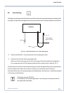
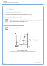
REMOVAL OF THE PHOTOMETER ASSEMBLY
Fig. 24-1: Analyzer Photometer Assembly
(2 channel IR analyzer, viewed from the front panel side)
1 Fastening screw, photometer assembly mounting bracket
2 Light source with mounting flange
3 Temperature sensor
4 Zero level adjustment baffle (not for sealed version)
5 Light source mounting screw
4
5
32
1
5
1