


24 - 7
REPLACEMENT AND CLEANING OF PHOTOMETRIC COMPONENTS
ETC00781(4) Series 100 e 02/2004
24.6 Physical Zeroing
Adjustment of the physical zero - level will only be required if a light source, a filter cell, or an analysis
cell have been replaced or repositionned.
Be sure to observe the safety measures !
Take care of the photometer temperature: Photometers heat up when powered!
Needed for the adjustment are a digital voltmeter (DVM) with a range of 2 VDC and a 3 mm
hexagon wrench SW 3.
P Switch on the analyzer (cf. chapter 6).
P Admit zero gas to the analyzer.
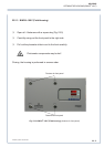
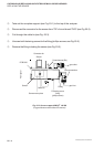
P Connect the DVM to the measuring points:
X 25 and X 28 ( ⊥ ) for channel 1 (IR measurement only).
X 27 and X 28 ( ⊥ ) for channel 1 (Combined Oxygen / IR measurement).
channel 2 (IR measurement only).
Depending on the installed photometer model continue with step 24.6.1 or 24.6.2
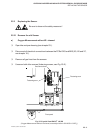
24.6.1 Standard Photometer (not sealed version)
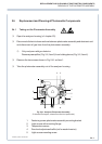
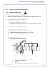
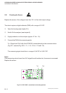
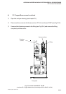
P Slightly loosen the light source mounting screws (shown in Fig. 24-1 as Item 5) or the
temperature sensor (shown in Fig. 24-1 as Item 3) resp. for channel 1 or channel 2.
P Set the zero level precisely to 0 V (± 100 mV) by turning the corresponding light source.
If the turning of the light source is not sufficient, the zero point can be adjusted by sliding
the zero level adjustment baffle (Fig. 24-1, item 4).
P Tighten the light source mounting screws (shown in Fig. 24-1 as Item 5) or the
temperature sensor (shown in Fig. 24-1 as Item 3) resp. for channel 1 or channel 2.
When the physical zeroing has been correctly set, perform an electrical zeroing (see chapter 9.).
PHYSICAL ZEROING