


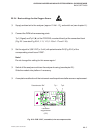


TECHNICAL DATA
27 - 3
ETC00781(4) Series 100 e 02/2004
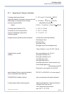
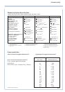
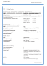
27.3 Signal Inputs / Outputs, Interfaces
2 analog outputs per channel 0 - 10 V and 0 - 20 mA (R
B
< 500 W)
[(optically isolated: 2 channels, common ground), or
offset (begin of range)and end of range 2 - 10 Vand 4 - 20 mA (R
B
< 500 W),
are free programmable] adjustable via keyboard
Option: 0 (0.2) - 1 V and 0 (4) - 20 mA (R
B
< 500 W)
3 analog inputs (Option for TC), 0 - 10 V, 0 - 20 mA,
for electronic cross compensation 2 - 10 V, 4 - 20 mA,
of up to 3 interfering components 0 - 1 V or 0.2 - 1 V
(external signals)
8 digital outputs, parallel (optically isolated) 2 threshold contacts per channel,
Sample gas valve,
Zero gas valve,
Span gas valve 1,
Span gas valve 2 (dual channel only)
“Open Collector”, max. 30 V DC / 30 mA
7 digital inputs, parallel Zero gas calibration ch.1 & ch.2,
(Option) Span gas calibration ch.1,
Span gas calibration ch.2,
open Zero gas valve,
open Span gas valve 1,
open Span gas valve 2 (dual channel only)
close Sample gas valve/
sample gas pump Off
Description: see chapter 13 and 29.8!
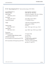
serial interface (Option, optically isolated) RS 232 C or RS 485 (2 or 4 wire support)
(not in combination with field bus)
FOUNDATION
™
fieldbus (Option) (not in combination with serial interface)
3 output relays (Option status signals) “Measure/Calibration” / “Failure Analyzer” /
“Sample Gas Pump On/Off”
“non-voltage carrying contacts”
max. 30 V / 1 A / 30 W
SIGNAL OUTPUTS, INTERFACES