


2-1
Chapter 2
Theory of Operation
Introduction
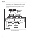
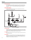
The RUSKA 7350’s power supply, electronics, pneumatics, and sensor combine to form
a complete, stand-alone, measure and control instrument. This portion of the manual
breaks the RUSKA 7350 down into its component modules (Figure 2-1) and provides a
general discussion of each.
Power Supply
The RUSKA 7350 is set up as either a 120 – 130 VAC, 50/60 Hz or 220 – 240 VAC,
50/60 Hz single phase as required by customer. Check label next to power supply inlet.
Electronics Section
The RUSKA 7350’s electronics section consists of the Back Plane Board, the
Microprocessor Board, the 76XX Interface Board, the Option Board, the IEEE interface,
and the Front Panel consisting of display and key pad.
Back Plane Board
The Microprocessor Board, the 76XX Interface Board, the Option Board, and the IEEE
Board plugs into the Back Plane Board.
The four voltages produced by the Power Supply are distributed to the Back Plane Board,
where they are conditioned to produce four additional voltages of +5 VDC, -5 VDC,
+12 VDC, and -12 VDC for analog use. The resulting seven DC voltages are then used
either directly or indirectly throughout the entire RUSKA 7350.
Microprocessor Board
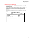
All of the RUSKA 7350’s software resides in nonvolatile, programmable, read-only
memory (Flash EPROM) on the Microprocessor Board, which plugs directly into the
Control Board. This software contains all of the instructions that operate the
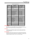
RUSKA 7350, as well as the conversion factors that the RUSKA 7350 uses to translate
the detected pressure into the units selected by the user. These factors are given in
Table 2-1.
Data that is subject to change after the RUSKA 7350 leaves the factory is held in
electrically erasable, programmable, read-only memory (EEPROM) on this Board.
This includes the current units of measure, the coefficients from the zeroing process,
the current pressure medium, and the conversion factors for the four user-defined units
of measure.
When the RUSKA 7350 powers up, its software is loaded into random access memory
(RAM), which is also on the Microprocessor Board. At the same time, the values stored
in EEPROM on the Board are restored to memory.