


RUSKA 7350
Users Manual
2-4
76xx Interface Board
This board interfaces and conditions the pump position signal. The board interfaces
these signals between the electronic and pneumatic module. This board also provides
a 0 – 10 VDC signal to 0 – 100 psi electronic pneumatic regulators and the motor
controller.
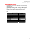
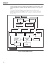
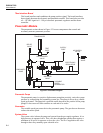
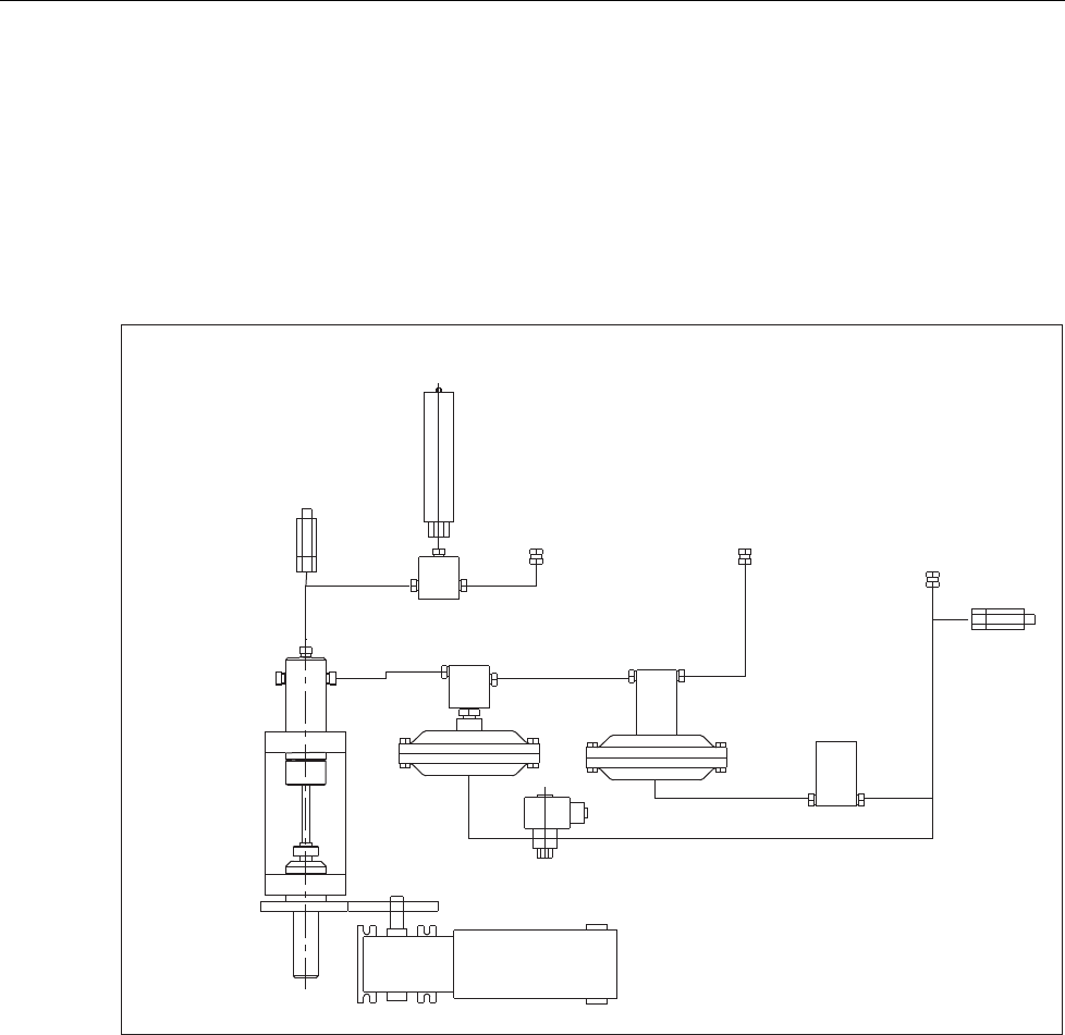
Pneumatic Module
The pneumatic section shown in Figure 2-2 houses components that control and
accurately measure pneumatic pressure.
TRANSDUCER
RELIEF
VALVE
RELIEF
VALVE
ELECTRONIC
REGULATOR
SOLENOID
VALVE
PNEUMATIC
PUMP
VARIABLE
SPEED
GEARMOTOR
AIR-OPERATED
VALVE
TEST
PORT
SUPPLY
PORT
AIR SUPPLY
110 PSI
gld02.eps
Figure 2-2. Pneumatic Diagram
Pneumatic Pump
The pneumatic pump is a positive displacement pump that precisely varies the system
pressure by compressing and expanding system gas. The pump is driven by a variable
speed gear-motor. The pump has a position sensor that tracks the position of the pump
plunger. It has two travel limit switches at each end of its stroke.
Gearmotor
The variable-speed gear motor drives the pneumatic pump. The gear box on the motor
reduces the motor speed.
System Valve
The system valve isolates the pump and system from the gas supply regulators. It is a
high pressure air-operated valve. This valve has a diaphragm operator that requires a
minimum of 60 psi of air pressure to close the valve. The air is supplied to this valve
through a three-way normally-open solenoid valve.