


TROUBLESHOOTING & REPAIR
F-49 F-49
RANGER 305D
Return to Section TOC Return to Section TOC Return to Section TOC Return to Section TOC
Return to Master TOC Return to Master TOC Return to Master TOC Return to Master TOC
FLASHING VOLTAGE TEST (continued)
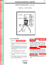
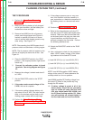
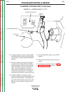
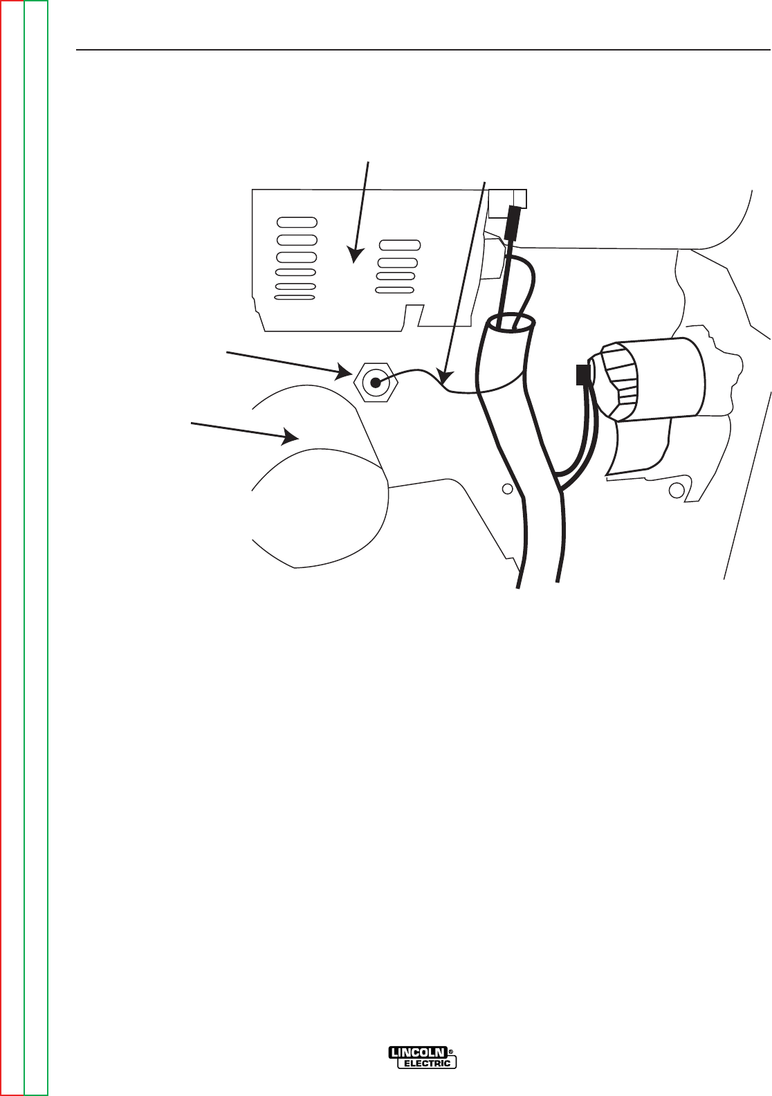
FIGURE F.11 – EXCITER LEADS T1, T2, T3
ENGINE ALTERNATOR
OIL FILTER
OIL PRESSURE SWITCH
#229
16. If battery voltage is present at leads #210H
and #224B, but not present at leads #200N
The Control PC board is probably defective.
Replace.
17. If battery voltage is present at lead #210H,
but not present at leads #224B or #200N
check the engine protection wiring and CR1
engine protection relay, per the wiring dia-
gram. Also check that the oil pressure
switch lead, (lead #229) has not come into
contact with chassis ground.
The engine
protection light should be off during this tes
t.
18. If battery voltage is not present at lead
#210H, check wiring per wiring diagram, and
check the run/stop switch. Also check the
ground PC board chassis ground wire, lead
#5K and the stud where it connects to the
chassis.
19. Set the RUN/STOP switch to the “STOP”
position.
20. Re-connect lead #229 to the oil pressure
switch.
21. If testing is completed, perform the Case
Cover Replacement procedure.