


Return to Section TOC Return to Section TOC Return to Section TOC Return to Section TOC
Return to Master TOC Return to Master TOC Return to Master TOC Return to Master TOC
GENERAL DESCRIPTION
The Ranger 305D is a diesel engine-driven welding
power source capable of producing 300 amps at
29VDC at a 100% duty cycle. The engine is coupled to
a brush-type alternating current generator. This AC
output is rectified then controlled by Chopper
Technology to produce DC current for multi-purpose
welding applications. The Ranger 305D is also capa-
ble of producing 9,500 watts (10,000 watts peak) of AC
auxiliary power at 100% duty cycle.
Battery, Engine, Engine Protection,
and Charging System.
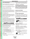
BATTERY:
The 12VDC battery powers the engine starter motor,
glow plug circuit, engine protection circuit, fuel pump
(codes 10926 and 11121), and fuel solenoid. Power is
also supplied to other components.
Starting the engine:
Starting the engine first requires that the Run/Stop
switch be in the run position. The glow plug button is
then pressed and held; this preheats the engine to
enhance starting and also temporarily provides power
to the fuel pump (codes 10926 and 11121), and fuel
solenoid hold coil.
The start button is pressed while still holding the glow
plug button. The start button cranks the engine and
powers the fuel solenoid pull cord.
The engine starts, builds oil pressure, and spins the
engine alternator, which begins charging the battery.
The charging system indicator light (code 10926), and
the engine protection indicator will turn off. When the
engine protection light turns off, the fuel pump (codes
10926 and 11121), and fuel solenoid are receiving
power from the engine protection circuit. The operator
can now release the glow plug button.
The engine protection system now monitors the oil
pressure and coolant temperature sensors. If either
sensor detects a fault condition, the engine protection
indicator will light, and power will be interrupted to the
fuel solenoid, immediately shutting the engine off.
THEORY OF OPERATION
E-2 E-2
RANGER 305D
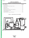
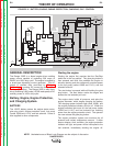
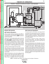
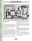
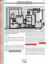
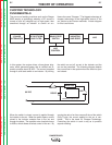
FIGURE E.2 – BATTERY, ENGINE, ENGINE PROTECTION, CHARGING, IDLE CONTROL
NOTE: Unshaded areas of Block Logic Diagram are the subject of discussion.
ROTOR
ENGINE
PROTECTION
CIRCUIT
ENGINE
PROTECTION
LIGHT
RUN
STOP
SWITCH
GLOW
PLUG
BUTTON
12V.
BATTERY
STARTER
ENGINE
ENGINE
SENSORS
GLOW
PLUGS
ENGINE
ALTERNATOR
START
BUTTON
IDLE
SOLENOID
PULL
COIL
HOLD
COIL
FUEL
PUMP
FUEL
SOLENIOD
PULL COIL
PULL COIL
PC BOARD
CHARGING
SYSTEM LIGHT
(CODE 10926 ONLY)
WELD
WINDING
STATOR
EXCITER
WINDING
120/240 VAC
AUX.WINDING
42 VAC
WINDING
240
VAC
CURRENT
SENSOR
14
PIN
120
vac
FLASHING
RECEPTACLES
HOLD COIL
6
PIN
AMPHENALS
OUTPUT
CONTROL
ARC
CONTROL
MODE
SWITCH
WELDING
TERMINAL
SWITCH
IDLE
SWITCH
AMP
DISPLAY
VOLT
DISPLAY
WELD CONTROL
P.C. BOARD
POWER
MODULE
IGBTs
SHUNT
+
CHOKE
-