


Return to Master TOC Return to Master TOC Return to Master TOC Return to Master TOC
Section F-1 Section F-1
RANGER 305D
Troubleshooting & Repair Section ................................................................................Section F
How to Use Troubleshooting Guide.......................................................................................F-2
PC Board Troubleshooting Procedures .................................................................................F-3
Troubleshooting Guide................................................................................................F-4 - F-20
Test Procedures...................................................................................................................F-21
Case Cover Removal and Replacement Procedure ....................................................F-21
Chopper Module Capacitor Discharge Procedure ........................................................F-23
Fuel Shutdown Solenoid Test........................................................................................F-25
Engine Throttle Adjustment Test....................................................................................F-29
Idler Solenoid Test.........................................................................................................F-33
Engine Alternator Test ...................................................................................................F-35
Brush and Slip Ring Service Procedure........................................................................F-37
Rotor Resistance and Ground Test ...............................................................................F-39
Rotor Resistance and Ground Test ...............................................................................F-41
Rotor Voltage Test .........................................................................................................F-43
Flashing Voltage Test ....................................................................................................F-47
Stator Voltage Test .......................................................................................................F-51
Stator Short Circuit & Ground Test ...............................................................................F-55
Output rectifier Bridge Test ...........................................................................................F-57
Chopper Module Function Test ....................................................................................F-61
Chopper Module Resistance Test ................................................................................F-65
Weld Control Board PWM Gate Signal Test ................................................................F-69
Weld Control Feedback Test .........................................................................................F-71
Control Potentiometer and Mode Switch Resistance Test ............................................F-75
Remote Receptacle Test ...............................................................................................F-79
Replacement Procedures ....................................................................................................F-83
Output Rectifier Bridge and Choke Removal and Replacement...................................F-83
Chopper Module Removal and Replacement ...............................................................F-87
Engine/Stator/Rotor Removal and Replacement ..........................................................F-91
Oscilloscope Waveforms......................................................................................................F-97
Normal Open Circuit Voltage Waveform (120 VAC Supply)..........................................F-97
Normal Open Circuit Voltage Waveform (Stick) ............................................................F-98
Normal Weld Voltage Waveform (Stick CC)..................................................................F-99
Normal Open Circuit Voltage Waveform (Wire CV Tap)..............................................F-100
Normal Weld Voltage Waveform (Wire CV) ................................................................F-101
Retest After Repair.............................................................................................................F-102
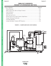
TABLE OF CONTENTS
TROUBLESHOOTING & REPAIR SECTION