


Return to Section TOC Return to Section TOC Return to Section TOC Return to Section TOC
Return to Master TOC Return to Master TOC Return to Master TOC Return to Master TOC
TROUBLESHOOTING & REPAIR
F-53 F-53
RANGER 305D
STATOR VOLTAGE TESTS (continued)
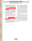
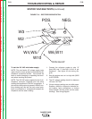
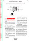
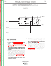
FIGURE F.13 – RECTIFIER BRIDGE DETAIL
POS.
NEG.
W3
W2
W1
W4,W5
W10
W6,W11
FROM SHUNT
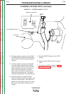
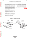
To test the 120 VAC wire feeder supply:
NOTE: The wire feeder AC voltage supply tests
require that the meter probes be inserted into the
Amphenol connection cavities. Care should be
taken to avoid damaging or expanding the termi-
nals when inserting the probes.
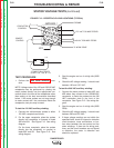
NOTE: The 120 VAC power supplied to the 14 pin
Amphenol connector originates from the same
winding that supplies the 120 VAC receptacles. If
the machine has previously passed 120VAC aux-
iliary winding test, this test can only reveal prob-
lems in connections or components between the
Amphenol and the stator winding.
1. Connect the voltmeter probes to pins “A”
(lead #32) and “J” (lead #31) of the 14 pin
Amphenol. See figure #3 and wiring dia-
gram.
2. Start the engine and run it at high idle (3625
to 3675 RPM).
3. The AC voltage reading should be between
120 and 135* VAC.
4. If these voltage readings are not within spec-
ifications, check for a tripped or defective cir-
cuit breaker, faulty connections, or broken
wires between the test points and the stator
windings. See wiring diagram.