


Return to Section TOC Return to Section TOC Return to Section TOC Return to Section TOC
Return to Master TOC Return to Master TOC Return to Master TOC Return to Master TOC
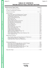
TROUBLESHOOTING & REPAIR
F-4 F-4
RANGER 305D
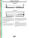
If for any reason you do not understand the test procedures or are unable to perform the test/repairs safely,
contact the Lincoln Electric Service Department for electrical troubleshooting assistance before you proceed. Call
1-888-935-3877.
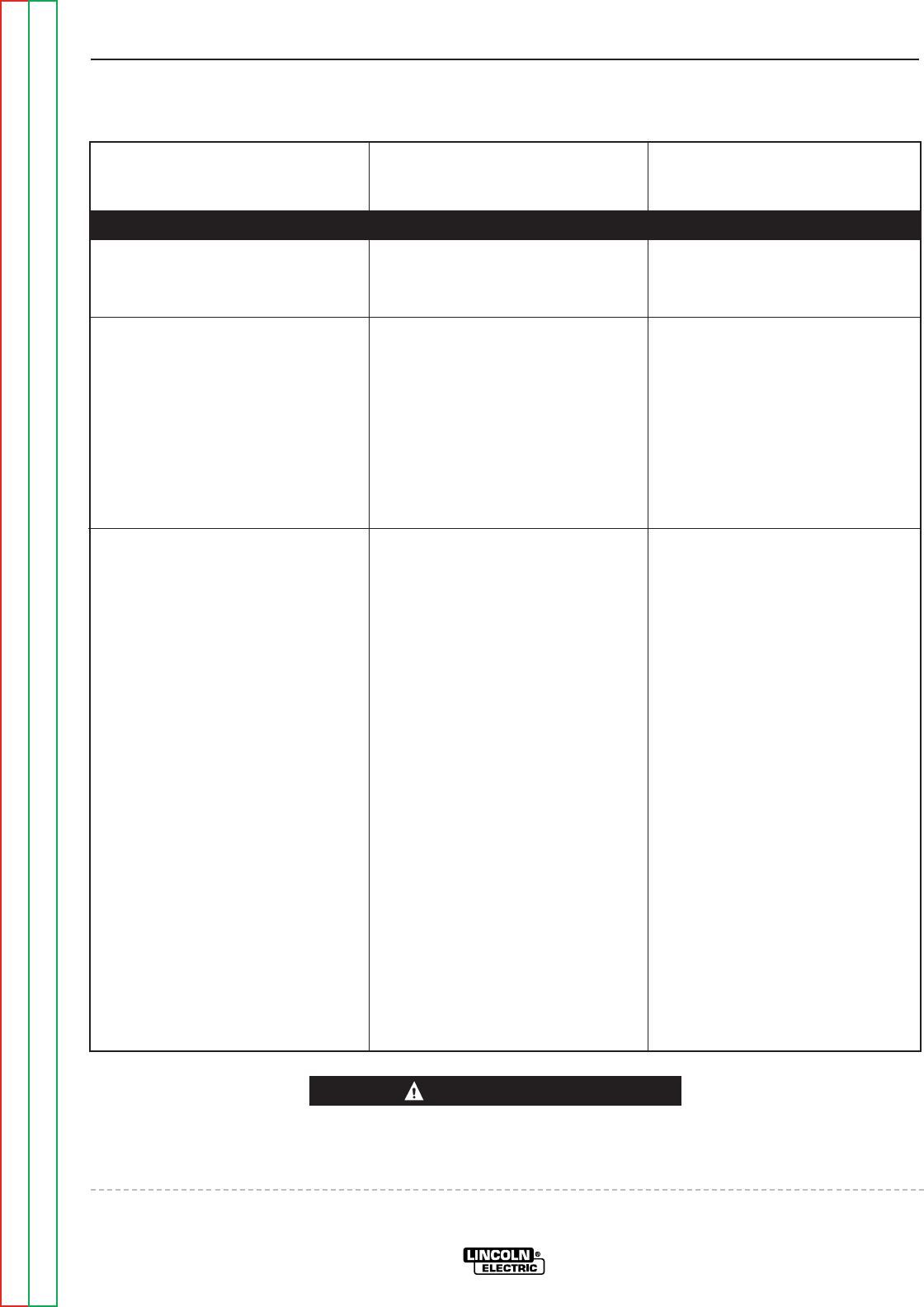
PROBLEMS
(SYMPTOMS)
POSSIBLE AREAS OF
MISADJUSTMENT(S)
RECOMMENDED
COURSE OF ACTION
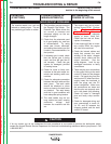
POWER OUTPUT PROBLEMS
Major mechanical or electrical
damage is evident.
1. Contact your local Lincoln
Authorized Field Service
Facility.
1. Contact the Lincoln Electric
Service Department at 1-888-
935-3877.
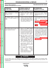
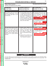
No welding output or auxiliary
power. The engine operates nor-
mally.
1. Check for loose or faulty con-
nections at any leads, cables or
cords attached to either the aux-
iliary output receptacles and/or
the weld output terminals.
1. Check the brushes for wear and
proper contact to the rotor slip
rings.
2. Perform the Brush and Slip
Ring Service procedure.
3. Perform the Rotor Voltage Test.
4. Perform the Stator Voltage
Test.
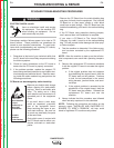
CAUTION
Observe Safety Guidelines
detailed in the beginning of this manual.
TROUBLESHOOTING GUIDE
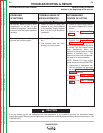
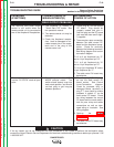
No welding output in any mode.
The auxiliary output is normal. The
engine operates normally.
1. Place the Welding Terminals
switch in the “WELD TERMI-
NALS ON” position. If the prob-
lem is solved, the fault may be in
the external control cable, or the
attached wire feeder, amptrol,
arc start switch, etc. (if used)
2. With the engine at high idle
(3650RPM), the machine in the
CC-STICK mode, the output
control at maximum, and the
welding terminals switch in the
“WELD TERMINALS ON” posi-
tion; check for the presence of
approximately 58VDC, OCV
(open circuit voltage) at the weld
output terminals.
3. If the correct OCV is present at
the welding output terminals,
check the welding
cables,connectors, work
clamps, electrode holder, etc. for
loose or faulty connections.
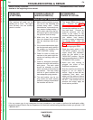
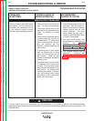
1. Check for damaged conductors
or faulty connections on the
heavy current carrying leads
that connect the output studs to
the Chopper module and to the
output Rectifier. Also Check
the shunt and choke assem-
blies for damage and faulty
connections.
2. Perform the Chopper Module
Function Test.