


TROUBLESHOOTING & REPAIR
F-80 F-80
RANGER 305D
Return to Section TOC Return to Section TOC Return to Section TOC Return to Section TOC
Return to Master TOC Return to Master TOC Return to Master TOC Return to Master TOC
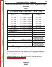
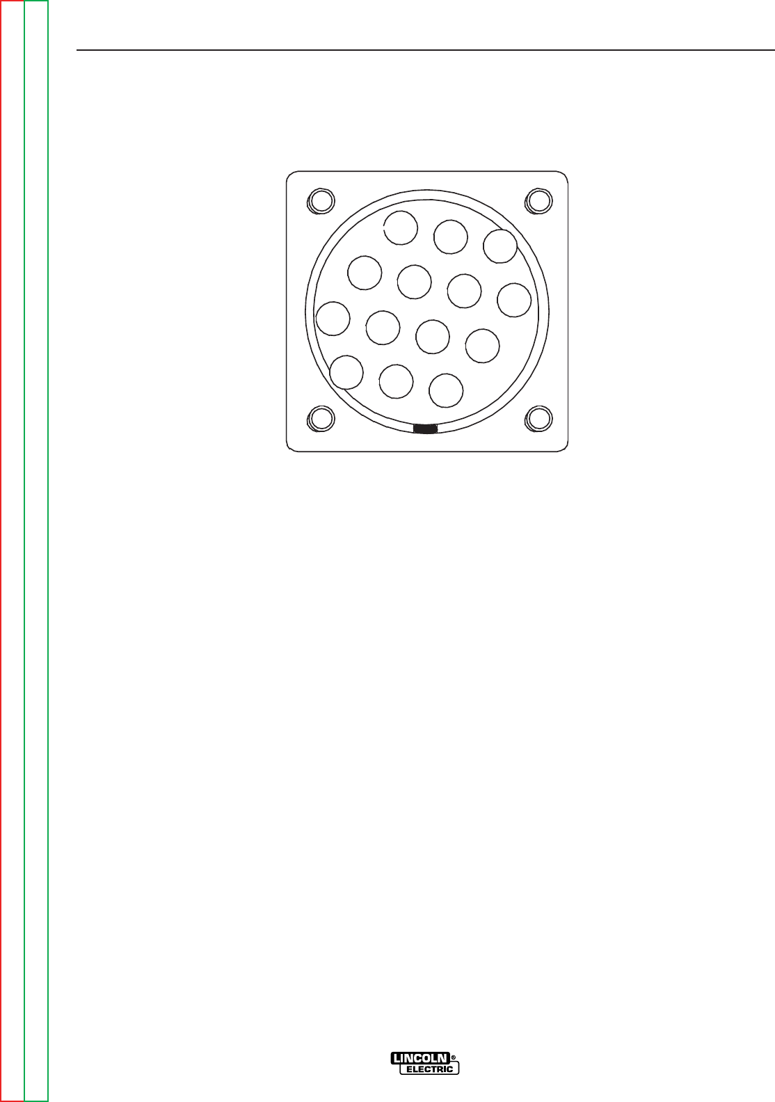
REMOTE RECEPTACLE RESISTANCE TEST (continued)
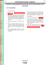
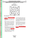
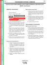
FIGURE F.18
AMPHENOL 1
E
C
D
A
B
L
K
J
M
N
F
G
H
I
TEST PROCEDURE
1. Turn the machine off.
2. Perform the Case Cover Removal
Procedure.
3. Make sure that there are no devices of any
kind plugged into either Amphenol recepta-
cles.
4. Remove Molex plug P1 from the control PC
board, see Control Inner-Connection
Diagram. Examine the Molex plug and the
receptacle on the control PC board for dirt,
corrosion, damaged or out-of-position pins.
Repair or replace any damaged components.
Position the P1 plug so it can not make elec-
trical contact with any other conductor or
chassis ground.
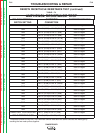
5. Perform the following resistance tests shown
in the following table. Be very careful not to
damage or spread any of the connection pins
in the Amphenol receptacle. See Table F.4.
6. If the measured resistance does not meet
values specified, check for damage, dirt or
moisture contamination in the Amphenol
receptacles and the P1 Molex plug. Check
for damaged or grounded wiring.
7. If the resistance values are found to be too
low, due to contaminated electrical compo-
nents in the Amphenol harness assembly.
Try removing the contamination and drying
the components completely. If the resistance
values are still too low, replace the Amphenol
harness assembly.
8. If the values are incorrect for the last two
tests in the table, (Pin C to Pin D) check the
welding terminal switch and the wiring con-
nected to that switch. See the wiring dia-
gram. Repair any faulty connections or
replace the switch if necessary.
9. Plug P1 back into the Control Pc board.
10. Perform the Case Cover Replacement
Procedure.