


TROUBLESHOOTING & REPAIR
F-77 F-77
RANGER 305D
Return to Section TOC Return to Section TOC Return to Section TOC Return to Section TOC
Return to Master TOC Return to Master TOC Return to Master TOC Return to Master TOC
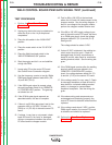
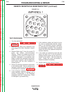
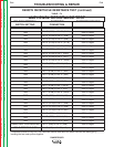
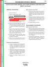
CONTROL POTENTIOMETER AND MODE SWITCH RESISTANCE TEST
(continued)
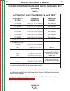
TABLE F.3
CC-STICK
P7-9 (#214) TO P7-14 (#218)
500K or Higher
CC-STICK
P7-9 (#214) TO P7-15 (#220)
500K or Higher
CC-STICK
P7-9 (#214) TO P7-16 (#222)
500K or Higher
CC-STICK
P7-14 (#218) TO P7-15 (#220)
500K or Higher
CC-STICK
P7-14 (#218) TO P7-16 (#222)
500K or Higher
CC-STICK
P7-15 (#220) TO P7-16 (#222)
500K or Higher
TOUCH START TIG
P7-15 (#220) TO P7-16 (#222) *
DOWNHILL PIPE
P7-14 (#218) TO P7-16 (#222)
*
CV-WIRE
P7-9 (#214) TO P7-16 (#222)
*
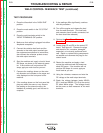
N/A
P7-5 (#75) TO P7-1 (#77)
about 10K
N/A
P7-1 (#77) TO P7-4 (#76)
Ohms values should
sweep smoothly from 10K
to 0 when ARC CONTROLis
turned from Min. to Max.
N/A
P7-6 (#279) TO P7-8 (#277)
about 10K
N/A
P7-8 (#277) TO P7-7 (#278)
Ohms values should
sweep smoothly from 10K
to 0 when ARC CONTROLis
turned from Min. to Max.
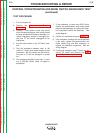
* Resistance should be very low, The Ohmmeter should read about the same value as
one would get by touching the two meter probes together.
If the resistance readings are not as specified in the table, replace the potentiome-
ter and mode switch plug and lead assembly, or replace the defective component.
See the Wiring Diagram.
if testing is complete, plug P7 back into the control PC board and perform the
Case Cover Replacement Procedure.
POT/MODE SWITCH RESISTANCE TEST
MODE SWITCH
SETTING
OHMMETER
CONNECTION
OHMMETER
READING