


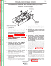

Removing the Rotor
1. Use the hoist and lifting straps to support
the rotor assembly.
2. Remove the screws and disc clamping bars
from the rotor coupling disc, and remove the
rotor.
NOTE: earlier machines used three 0.31” thick
clamping bars and later models use six 0.14”
thick camping bars arranged in three sets of two
bars each.
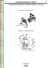
3. If the rotor is to be replaced, remove the
screws, rotor clamping ring and coupling
disc from the rotor hub.
Replacing the Rotor
1. Whenever the rotor and stator are separat-
ed, it is highly recommended that a new
bearing and tolerance ring be installed when
the rotor and stator are reassembled.
2. Examine the rotor, coupling disc, clamping
ring, clamping bars, screws, lock washers,
and the engine flywheel. Make sure that all
of the parts are clean and in good condition.
3. Install a new bearing on the rotor shaft.
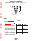
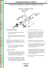
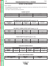
4. Assemble the coupling disc and clamping
ring to the rotor hub. The surface of the
disc with the stamping burrs should be
against the rotor hub. The side of the
clamping ring with the radius should be
placed against the coupling disc. See
Figure F.23.
5. Insert the screws with lock washers and
evenly tighten to a torque of 17 to 19 Ft-Lbs.
6. Lift the rotor assembly with the hoist and lift-
ing straps and recheck the engine flywheel
and coupling disc for anything that might
prevent proper seating.
7. To attach the coupling disk to the engine fly-
wheel, align the screw holes and insert the
six screws, with lock washers, through the
dsc clamping bars and the coupling disc and
into the engine flywheel.
8. Evenly tighten all the screws to a torque of
17 to 19 Ft-Lbs.
TROUBLESHOOTING & REPAIR
F-95 F-95
RANGER 305D
Return to Section TOC Return to Section TOC Return to Section TOC Return to Section TOC
Return to Master TOC Return to Master TOC Return to Master TOC Return to Master TOC
STATOR/ROTOR REMOVAL AND REPLACEMENT (continued)
FIGURE F.23 – DISC/RING LOCATION
COUPLING
DISC
CLAMPING
RING