


OPERATION
B-8 B-8
RANGER 305D
Return to Section TOC Return to Section TOC Return to Section TOC Return to Section TOC
Return to Master TOC Return to Master TOC Return to Master TOC Return to Master TOC
TIG WELDING
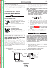
The TOUCH START TIG setting of the MODE switch is for DC
TIG (Tungsten Inert Gas) welding. To initiate a weld, the OUT-
PUT control is first set to the desired current and the tungsten is
touched to the work. During the time the tungsten is touching the
work there is very little voltage or current and, in general, no
tungsten contamination. Then the tungsten is gently lifted off the
work in a rocking motion, which establishes the arc.
The ARC CONTROL is not active in the TIG mode.
The Ranger 305D can be used in a wide variety of DC TIG weld-
ing applications. In general the “Touch Start” feature allows con-
tamination-free starting without the use of a Hi-frequency unit. If
desired, the K930-2 TIG Module can be used with the Ranger
305D. See Table B.2 for reference settings.
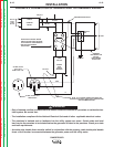
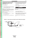
Ranger 305D settings when using the K930-2 TIG Module with
an Amptrol or Arc Start Switch:
a. Set the MODE Switch to the TOUCH START TIG setting.
b. Set the “IDLER” Switch to the “AUTO” position.
c. Set the “WELD TERMINALS” switch to the “REMOTELY
CONTROLLED” position. This will keep the solid state con-
tactor open and provide a “cold” electrode until the Amptrol or
Arc Start switch is pressed
When using the TIG Module, the OUTPUT control on the Ranger
305D is used to set the maximum range of the CURRENT.
WIRE WELDING-CV
Connect a wire feeder to the RANGER 305 D according to the
instructions in INSTALLATION INSTRUCTIONS Section.
In the CV-WIRE mode, the Ranger 305D can be used with a
broad range of flux cored wire (Innershield and Outershield)
electrodes and solid wires for MIG welding (gas metal arc weld-
ing). Welding can be finely tuned using the ARC CONTROL.
Turning the ARC CONTROL clockwise for -10 (soft) to +10
(crisp) changes the arc from soft and washed-in to crisp and nar-
row. It acts as an inductance control. The proper setting
depends on the procedure and operator preference. Start with
the dial set at 0.
Some recommended Innershield electrodes are: NR-311, NS-
3M, NR-203 Ni 1%, NR-204H. Recommended Outershield elec-
trodes are :0S-70, OS-71M.
Some recommended solid wires for MIG welding are: .035
(0.9mm), and .045 (1.1mm), L-50 and L-56, .035 (0.9 mm) and
.045 (1.1mm) Blue Max MIG 308 LS.
For any electrodes, including those above, the procedure should
be kept within the rating of the machine.
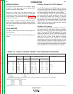
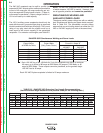
ARC GOUGING
The RANGER 305D can be used for limited arc goug-
ing. For optimal performance, set the MODE switch to
CC-STICK and the ARC CONTROL to +10.
Set the OUTPUT CONTROL knob to adjust output cur-
rent to the desired level for the gouging electrode being
used according to the ratings in the following Table B.3
Carbon Diameter
Current Range (DC, electrode
positive)
1/8" 75-140 Amps
5/32" 90-150 Amps
3/16" 200-250 Amps
AUXILIARY POWER
Be sure that any electrical equipment plugged into the generator
AC power receptacles can withstand +/- 10% voltage and a +/-
3% frequency variation.
-----------------------------------------------------------------------
Start the engine and set the IDLER control switch to
the desired operating mode. Full power is available
regardless of the welding control settings as long as no
welding current is being drawn.
The auxiliary power of the Ranger 305D consists of
two 20 amp-120 VAC (5-20R) duplex receptacles and
one 50 amps 120/240 VAC (14-50R) receptacle. The
240 VAC receptacle can be split for single-phase 120
VAC operation.
The auxiliary power capacity is 10,000 watts peak,
9,500 watts of continuous 60 Hz, singe-phase power.
The auxiliary power capacity rating in watts is equiva-
lent to volt-amperes at unity power factor. The maxi-
mum permissible, 40 amps continuous current of the
240 VAC output is 42 amps maximum.
NOTE: Machines with code numbers of 11121 and
higher are equipped with GFCI duplex receptacles. If
a GFCI receptacle is “tripped”, it will not reset unless
it is receiving nearly full voltage from the generator; for
this reason, the engine must be running at high RPM
before resetting a GFCI.
TABLE B.3 - CURRENT RANGE
PER ELECTRODE DIAMETER
WARNING