


K18161 FULL KVA ADAPTER KIT
Plugs into the 120/240V NEMA 14-0R receptacle on
the casefront (which accepts 4-prongs plugs) and con-
verts it to a NEMA 6-50R receptacle, (which accepts 3-
prong plugs.)
CONNECTION OF LINCOLN
ELECTRIC WIRE FEEDERS
ELECTRIC SHOCK can kill.
. Do not operate with panels open.
. Disconnect NEGATIVE (-) BATTERY
LEAD before servicing.
. Do not touch electrically live parts.
MOVING PARTS can injure.
. Keep guards in place.
. Keep away from moving parts.
. Only qualified personnel should
install, use or service this equipment.
------------------------------------------------------------------------
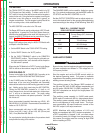
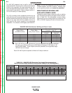
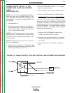
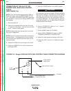
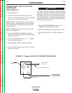
CONNECTION OF THE RANGER 305D TO
WIRE FEEDERS USING K867 UNIVERSAL
ADAPTER (SEE FIGURE C.1)
NOTE: When you use the Ranger 305D with non-
Lincoln Electric wire feeders or with certain earlier
models of Lincoln wire feeders, you will require the
K867 Universal Adapter. The following discussion and
connection diagram explain in general how to make the
proper connections.
1. Shut the welder off.
2. Connect the electrode cable from the wire feeder to
the “+” terminal of the welder. Connect the work
cable to the “-” terminal of the welder.
NOTE: Welding cable must be sized for current and
duty cycle of application.
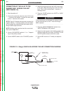
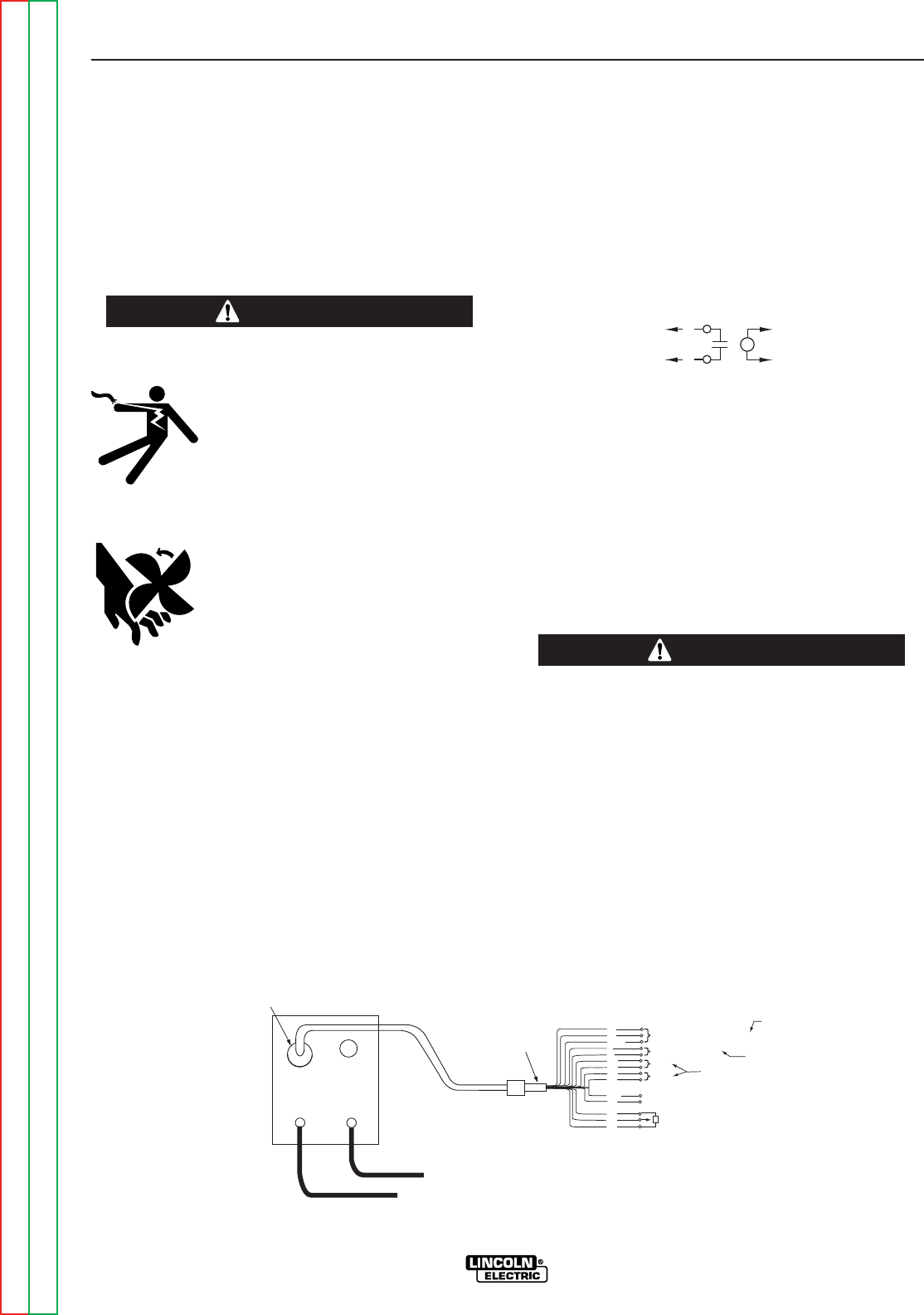
3. Connect the K867 Universal Adapter to the 14-pin
amphenol of the Ranger 305D as shown in Figure
C.1. Make the proper connections for local or
remote control according to Figure C.1. and the fol-
lowing NOTES, indicated on the figure:
A. These leads are not used for the Ranger
305D. Insulate each unused lead individually.
B. For wire feeders that return a signal for weld-
ing output, use an isolation relay to close
leads 2 and 4.
C. Refer to the Operation section of this manual
for maximum wire feeder auxiliary current
draw.
4. Set the “MODE” switch to the “CV-WIRE” position.
5. Place the “IDLER” switch in the “AUTO” position.
Any increase of the high idle engine RPM by chang-
ing the governor setting or overriding the throttle link-
age will cause an increase in the AC auxiliary voltage.
If this voltage goes over 140 volts, wire feeder control
circuit may be damaged. The engine governor setting
is preset at the factory - do not adjust above RPM
specifications listed in this manual.
------------------------------------------------------------------------
6. Set the “VOLTMETER” switch to “+” or “-” depend-
ing on the polarity chosen.
7. Set the ARC control to “0” initially and adjust to suit.
8. Adjust wire feed speed at the wire feeder.
ACCESSORIES
C-3 C-3
RANGER 305D
Return to Section TOC Return to Section TOC Return to Section TOC Return to Section TOC
Return to Master TOC Return to Master TOC Return to Master TOC Return to Master TOC
WARNING
81
82
4
2
SPARE
31
42
41
77
21
GND
32
75
76
POWER SOURCE FRAME CONNECTION
WIRE FEEDER VOLTMETER CONNECTION
CONNECTS TO (WORK TERMINAL) OF POWER SOURCE
10K
MIN.
REMOTE OUTPUT CONTROL
115 VAC
42 VAC
WELDING OUTPUT
CONNECT TOGETHER FOR
NOT USED ON RANGER POWER SOURCES
A
B
C
+
-
ELECTRODE CABLE
TO WIRE FEED UNIT
TO WORK
K867 UNIVERSAL
ADAPTER PLUG
14-PIN
AMPHENOL
FIGURE C.1 - Ranger 305D/K867 UNIVERSAL ADAPTER CONNECTION DIAGRAM
2
4
TO
K867
TO
WIRE
FEEDER
CAUTION