


THEORY OF OPERATION
E-4 E-4
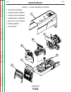
RANGER 305D
Return to Section TOC Return to Section TOC Return to Section TOC Return to Section TOC
Return to Master TOC Return to Master TOC Return to Master TOC Return to Master TOC
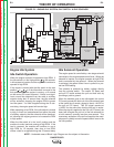
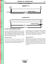
Generating Power
Flashing:
The battery supplies 12VDC power to the control PC
board. When the engine protection light shuts off, the
control board allows the 12VDC “flashing” voltage to be
applied to the now rotating generator field winding, first
passed through a current limiting resistor, then through
the brushes and slip rings to frame ground.
Building Output:
The flashing current produces a weak magnetic field in
the rotor. This rotating magnetic field begins to gener-
ate AC output from all of the stator windings. Output
form the 42 VAC exciter winding is rectified by a diode
bridge, then filtered by a capacitor and fed back into the
rotating field winding, through the brushes, making the
magnetic field stronger. This stronger magnetic field
then produces higher voltage from the stator windings,
which feeds back to the rotor, making its magnetic field
even stronger.
This process of strengthening the magnetic field
through feedback from the output continues to increase
the output of the main generator until the design volt-
age is reached. The output of the machine depends on
engine RPM and rotor current.
The field voltage is now considerably higher than the
flashing voltage that was used to start the generating
process. Circuitry in the control PC board blocks that
higher field voltage from intruding into the 12VDC bat-
tery system.
AC output:
The generator is now producing sufficient AC power
from all four of the windings. These windings consist of
60 to 65 VAC three phase weld winding, a 120/240 VAC
auxiliary power winding, a 42 VAC exciter winding, and
a 42 VAC wire feeder power winding.
DC output:
The output from the three phase weld winding is con-
verted to DC by a three phase output rectifier then fil-
tered by four large capacitors located on the power
module assembly. This produces about 90VDC power
that supplies the IGBTs on the power module and the
weld control PC board.
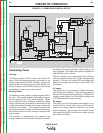
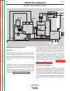
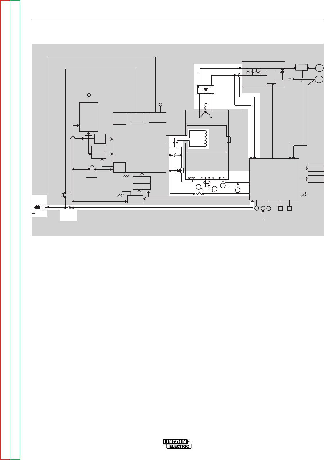
FIGURE E.4 – GENERATING POWER & OUTPUT
ROTOR
ENGINE
PROTECTION
CIRCUIT
ENGINE
PROTECTION
LIGHT
RUN
STOP
SWITCH
GLOW
PLUG
BUTTON
12V.
BATTERY
STARTER
ENGINE
ENGINE
SENSORS
GLOW
PLUGS
ENGINE
ALTERNATOR
START
BUTTON
IDLE
SOLENOID
PULL
COIL
HOLD
COIL
FUEL
PUMP
FUEL
SOLENIOD
PULL COIL
PULL COIL
PC BOARD
CHARGING
SYSTEM LIGHT
(CODE 10926 ONLY)
WELD
WINDING
STATOR
EXCITER
WINDING
120/240 VAC
AUX.WINDING
42VAC
WINDING
240
VAC
CURRENT
SENSOR
14
PIN
120
vac
FLASHING
RECEPTACLES
HOLD COIL
6
PIN
AMPHENALS
OUTPUT
CONTROL
ARC
CONTROL
MODE
SWITCH
WELDING
TERMINAL
SWITCH
IDLE
SWITCH
AMP
DISPLAY
VOLT
DISPLAY
WELD CONTROL
P.C. BOARD
POWER
MODULE
IGBTs
SHUNT
+
CHOKE
-