


Return to Section TOC Return to Section TOC Return to Section TOC Return to Section TOC
Return to Master TOC Return to Master TOC Return to Master TOC Return to Master TOC
TROUBLESHOOTING & REPAIR
F-44 F-44
RANGER 305D
ROTOR VOLTAGE TEST (continued)
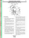
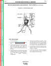
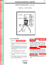
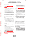
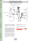
FIGURE F.10 – LEAD LOCATIONS
SLIP RINGS
BRUSHES
LEADS
201
5H
+
-
LEADS
200A
200
TEST PROCEDURE
1. Perform the Case Cover Removal proce-
dure.
2. Connect the voltmeter probes to the brush
terminals. See Figure F.10. See the wiring
diagram.
3. Set the RUN/STOP switch to “RUN” and
the IDLE switch to “HIGH”. Start the engine
and allow the RPM to stabilize for about 15
to 30 seconds.
The meter should read 46 to 54 VDC.
4. Set the RUN/STOP switch to “STOP”
5. If the meter reading is normal, this test is
complete.
6. If the voltage measures zero or very near
zero, the rotor flashing circuit may be faulty
or the rotor may be shorted.
7. Perform the Rotor Resistance and
Ground Test and the Rotor Flashing
Voltage Test.
8. If voltage is higher than 54 VDC, the
engine RPM may be too high, or there may
be voltage intrusion from one of the higher
voltage stator windings to the stator exciter
winding. Perform the Engine Throttle
Adjustment Test, and the Stator Short
Circuit and Ground Test.
9. If the voltage is lower than 46, but high-
er than 14, the engine RPM may be too
low, or there may be problems in the wind-
ings or other exciter circuit components or
connections. Perform the Engine Throttle
Adjustment Test, and then perform the
testing described below, under the heading
“If the voltage measures about 3 to 5
VDC”