


TROUBLESHOOTING & REPAIR
F-59 F-59
RANGER 305D
Return to Section TOC Return to Section TOC Return to Section TOC Return to Section TOC
Return to Master TOC Return to Master TOC Return to Master TOC Return to Master TOC
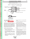
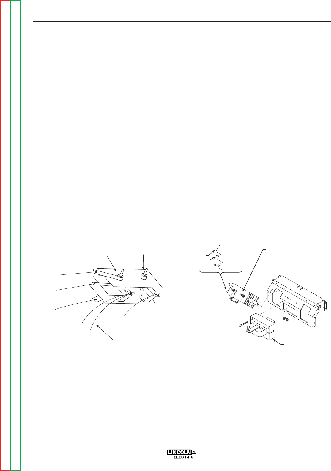
OUTPUT RECTIFIER BRIDGE TEST (continued)
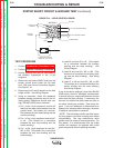
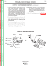
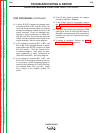
W1
W2
W3
OUTPUT
RECTIFIER
BRIDGE
TOP
CENTER
BOTTOM
CHOKE
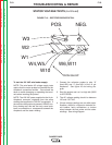
POS.
NEG.
W3
W2
W1
W4,W5
W10
W6,W11
FROM SHUNT
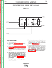
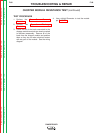
7. Check for grounds by placing one of the ohm
meter probes on a clean, unpainted metal
surface of the machine. Touch the other
probe to each of the five rectifier terminals.
The resistance to chassis ground from each
terminal should be very high, 500,000 (500K)
ohms minimum. If the resistance reading is
less than specified, the rectifier is grounded
and should be replaced.
8. If using diode checker or a multimeter with
diode check functionality, read and under-
stand the instructions that accompany your
test equipment.
9. If using an analog ohmmeter, the forward
bias test will indicate low resistance and the
reverse bias test will indicate high resistance.
Precise ohm values for this test will vary
depending on a test equipment used.
NOTE: A digital Ohmmeter is not recommended
for this test. A typical digital Ohmmeter
does not provide enough voltage or cur-
rent flow to reliably test the diodes used in
this rectifier.
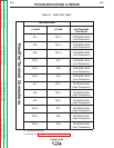
10. Test all of the diode groups per the Table F.1.
FIGURE F.16 – SHUNT/RECTIFIER LEADS
OR