


10
1. Determining catalog numbers
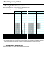
1. 5. Selecting I/O extension cards (VW3A58201, VW3A58202)
1. 5. 1. ATV38 and I/O option cards (VW3A58201, VW3A58202)
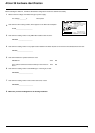
Required information: Connection diagram, presence of an I/O extension card
As standard the ATV 61 has more I/O than the ATV38.
• If the ATV38 is not equipped with an I/O extension card, there is no need to add a card to the Altivar 61. Ignore this section.
• If the ATV38 is equipped with an I/O extension card, it is important to know which inputs/outputs are used as well as the function assigned
to AI3 (VW3A58201 card) and to encoder input A, A
, B, B (VW3A58201 card).
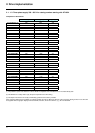
The tables below can be used to ascertain what was used previously and, therefore, to find the equivalent on ATV 61 with or without an
option card.
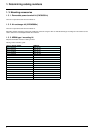
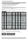
Scenario 1: Replacing an ATV38 with or without a VW3A58201 option card:
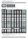
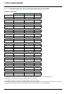
g Review of the various instances of use of the AI3 input on the VW3A58201 card:
AI3 assignment
Used: Becomes:
ATV38 ATV 61 Description VW3A58201 VW3 A3 201 VW3 A3 202 Description
R1A/R1B/
R1C
R1A/R1B/
R1C
Fault relay (R1) COM 0 V 0 V Common
R2A/R2C R2A/R2C Programmable relay (R2)
R3A/R3B/
R3C
R4A/R4B/
R4C
Programmable relay
AO 1 AO 1 0-20 mA analog output -10 -10 -10 -10 V output
COM COM Analog input common TH1+ TH2+ PTC probe
AI 1 AI 1+ 0…10 V analog input TH1- TH2- PTC probe
+10 +10
1 to 10 kΩ potentiometer
power supply
+24 +24 +24 Logic input power supply
AI 2 AI 2
Analog input
0…10 V 0..4/20 mA
LI 5 also on
control card
LI 7 LI 11
24 V DC programmable
logic input
LI 1 LI 1
24 V DC run forward logic
inputs
LI 6 also on
control card
LI 8 LI 12
24 V DC programmable
logic input
LI 2 LI 2
24 V DC programmable
logic input
LI 9 LI 13
24 V DC programmable
logic input
LI 3 LI 3
24 V DC programmable
logic input
LI10 LI 14
24 V DC programmable
logic input
LI 4 LI 4
24 V DC programmable
logic input
LO LO 1 LO 3 Logic output
+24 +24 Logic input power supply LO 2 LO 4 Logic output
LI 5
24 V DC programmable
logic input
LO + CLO CLO Logic output power supply
LI 6
24 V DC programmable
logic input
AI 3A/AI3 B
g
Current
AI3 +/AI3 -
Programmable analog input
AI4 Programmable analog input
AO AO 2
Programmable analog
output
AO 3
Programmable analog
output
+10 +10 V output
FP Pulse input
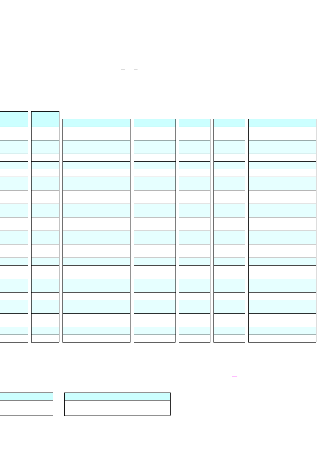
PTC Use LI6 on ATV 61 control card in PTC mode and adjust SW2 (see page xx
)
Use the TH inputs on the VW3 A3 201 or VW3 A3 202 option cards (see page xx
)
Speed reference Two different options
ATV38 ATV 61
AI3 (0..10 V) AI1 or AI2 if available
AI3 (+/- 10 V) AI1