


51
3. Implementation of the communication option cards
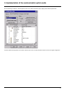
3. 8. 4. Configuring the drive in "ATV38 Interchangeability" mode
The following bus management parameters:
Time out, Peer Cop node, Control station, Number of registers are transferred by the PowerSuite software workshop with the same values
as they had in the Altivar 38.
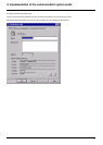
Configuring the drive control mode
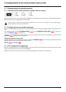
Check and configure the control mode applied to the drive in the [1.6 - COMMAND] (CtL-) menu on the graphic display terminal, the
integrated display terminal or the PowerSuite software workshop.
[Profile] (CHCF) = [8 serie] (SE8)
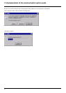
3. 8. 5. PLC configuration and application
The fact of opening the Altivar 61’s "ATV38 compatibility" memory zone (SE8 mode) performed by the PowerSuite software workshop
means that no changes need to be made in the PLC application.
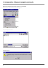
3. 8. 6. Communication fault
Modbus Plus communication faults are indicated by the red RD LED on the card.
Parameter
[Network fault] (CnF-) can be used to obtain more detailed information about the origin of the fault. It can only be accessed
on the graphic display terminal, in the
[1.10 DIAGNOSTICS] (dGt-) menu, [MORE FAULT INFO] (AFI-).
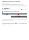
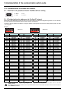
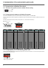
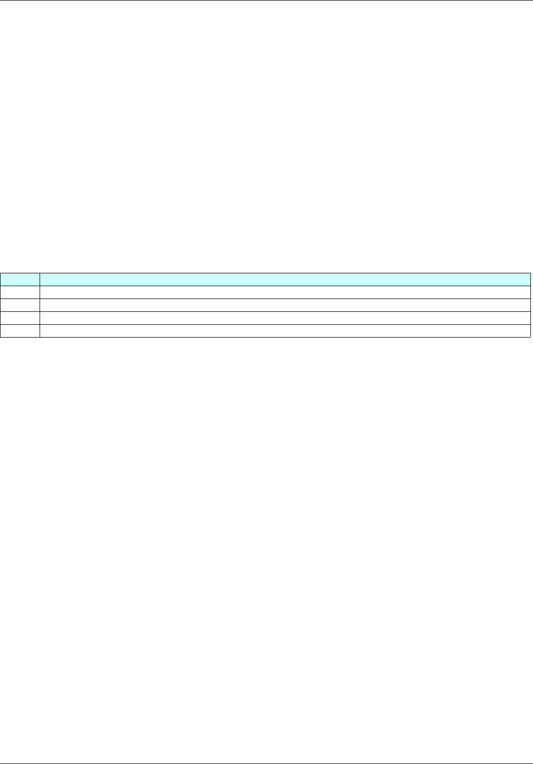
Value Description of the values of the [Network fault] (CnF-) parameter
0 No fault
1 Time out for receipt of periodic variables destined for the drive. This time out can be set by the network configuration software.
2 Master PLC changes from Run to STOP
3 Initialization fault on the Modbus Plus card (hardware problem)