


39
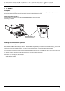
3. Implementation of the communication option cards
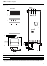
3. 2. Communication via Modbus network
3. 2. 1. Calculating the polarization resistors
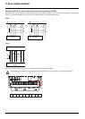
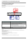
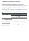
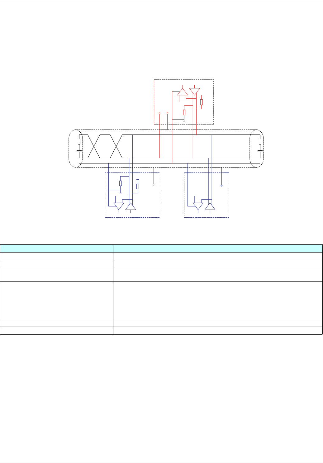
Mixed schematic
Slaves with 4.7 kΩ polarization can be integrated into a standard schematic. Suitable polarization resistance (Rp) must be calculated.
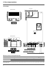
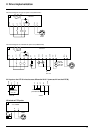
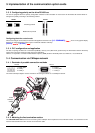
Schematic diagram
• To calculate the polarization resistance (Rp), all station polarizations must be deemed to be connected in parallel.
Example
If the bus Rp polarization is 470 Ω (installed in the master) and 2 slaves have 4700 Ω polarization, the equivalent polarization is:
1/Re = 1/470 + 1/4700 + 1/4700,
i.e., Re = 1/(1/470 + 1/4700 + 1/4700)
and, therefore, Re = 390 Ω
390 Ω is greater than 162 Ω, and the schematic is correct.
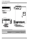
For an ideal equivalent polarization (650 Ω), Rp bus polarization can be installed so that:
1/650 = 1/Rp + 1/4700 + 1/4700,
i.e., Rp = 1/(1/650 - 1/4700 - 1/4700)
and, therefore, Rp = 587 Ω.
• If the master has 470 Ω polarization, up to 18 slaves with 4.7 kΩ polarization can be connected.
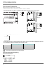
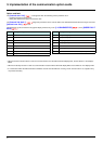
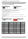
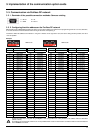
Type of trunk cable Shielded cable with 1 twisted pair and at least a 3
rd
conductor
Maximum length of bus 1000 m at 19200 bps
Maximum number of stations (without repeater) Up to 32 stations, i.e., 31 slaves (depending on Rp and the number of 4.7 kΩ resistors)
Maximum length of tap links • 20 m for a single tap link
• 40 m divided by the number of tap links on a multiple junction box
Bus polarization • One pulldown resistor at the 5 V (Rp)
• One pulldown resistor at the Common (Rp)
This polarization can be provided in the master.
The value of Rp should be validated (or determined) by calculating the equivalent
polarization (Re) according to the polarization of the master and slave stations.
The value of Re must be between 162 Ω and 650 Ω (recommended value: 650 Ω).
Line termination One 120 Ω 0.25 W resistor in series with a 1 nF 10 V capacitor
Common polarity Yes (Common)
1 nF
4,7 kΩ
4,7 kΩ
Rp
Rp
120 Ω
5 V
0 V
5 V
0 V
D1
Common
D0
R
T
T
R
T
R
Master
Slave 1
Slave n