


43
3. Implementation of the communication option cards
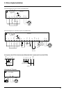
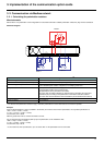
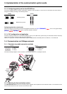
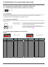
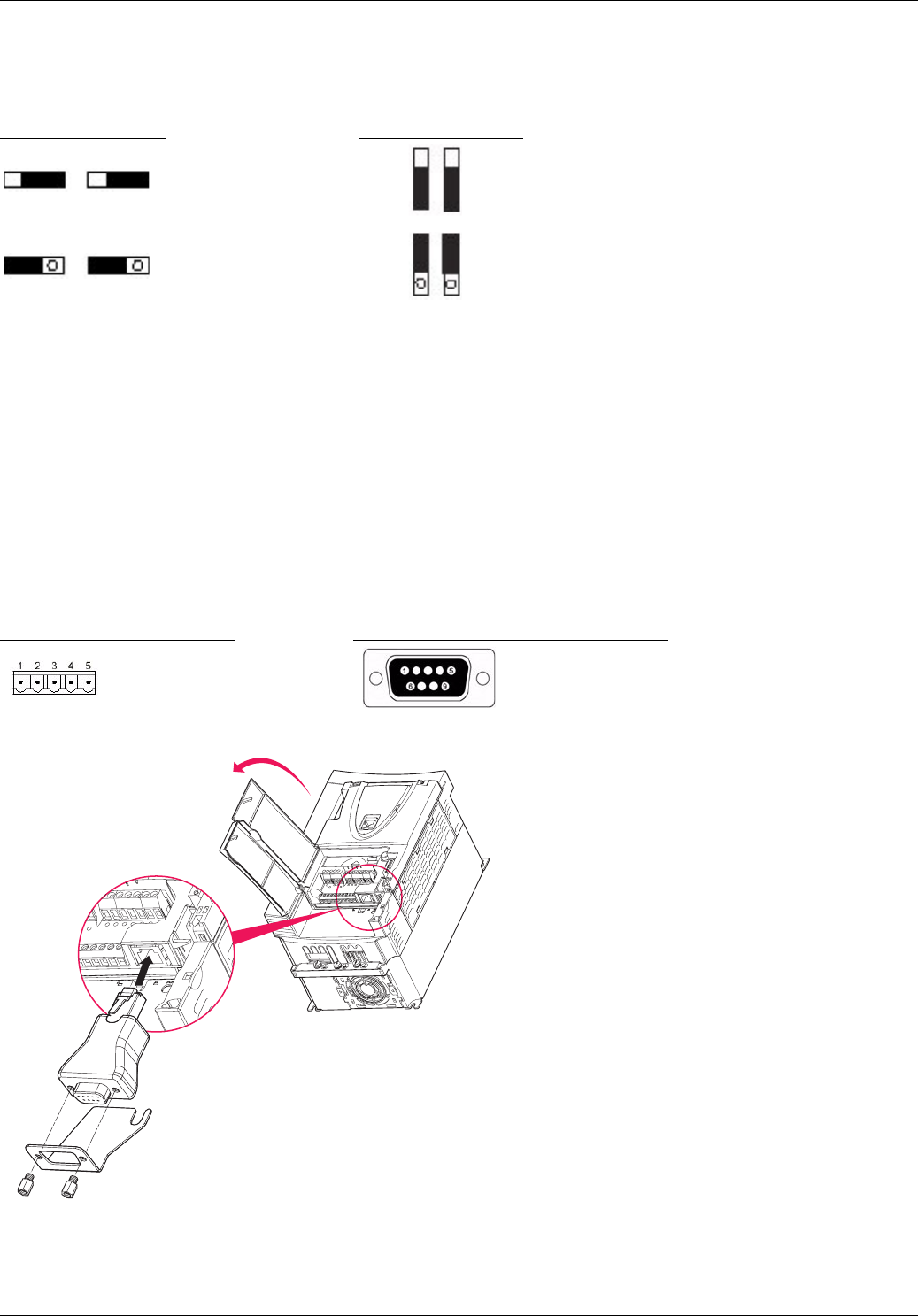
3. 3. 3. Configuring polarity on the drive RS 485 bus
The card is equipped with 2 line polarity configuration switches but the orientation is not the same for the Altivar 38 and the Altivar 61.
Configure the polarity according to the following method.
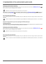
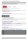
Configuring the drive control mode
Check and configure as necessary the control mode applied to the drive in the [1.6 - COMMAND] (CtL-) menu on the graphic display
terminal, the integrated display terminal or the PowerSuite software workshop.
[Profile] (CHCF) = [8 serie] (SE8)
3. 3. 4. PLC configuration and application
The fact of opening the Altivar 61’s "ATV38 compatibility" memory zone (SE8 mode) performed by the PowerSuite software workshop
means that no changes need to be made in the PLC application.
However, in response to a function 43 identification request (16#2B) the drive will identify itself as an Altivar 61, not an Altivar 38.
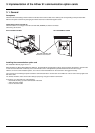
3. 4. Communication via CANopen network
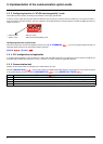
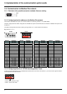
3. 4. 1. Reminder of possible connection methods
The ATV61 CANopen adapter must be used when connecting the Altivar 61 to a CANopen network.
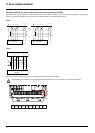
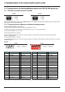
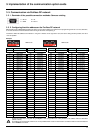
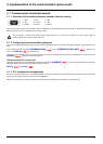
3. 4. 2. Matching the line termination resistor
The VW3 CAN KCDF 180T connector for connecting to the CANopen bus incorporates a line termination resistor. You should ensure this
has been activated when the drive is at the end of the trunk cable.
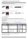
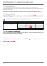
ATV38 ATV 61
Unitelway protocol
Modbus/Jbus protocol
ATV38 ATV 61
1 = CAN_GND
2 = CAN_L
4 = CAN_H
2 = CAN_L
3 = CAN_GND
7 = CAN_H
E.g., ATV61HU22M3
ATV61
CANopen
adapter