29
2. Drive implementation
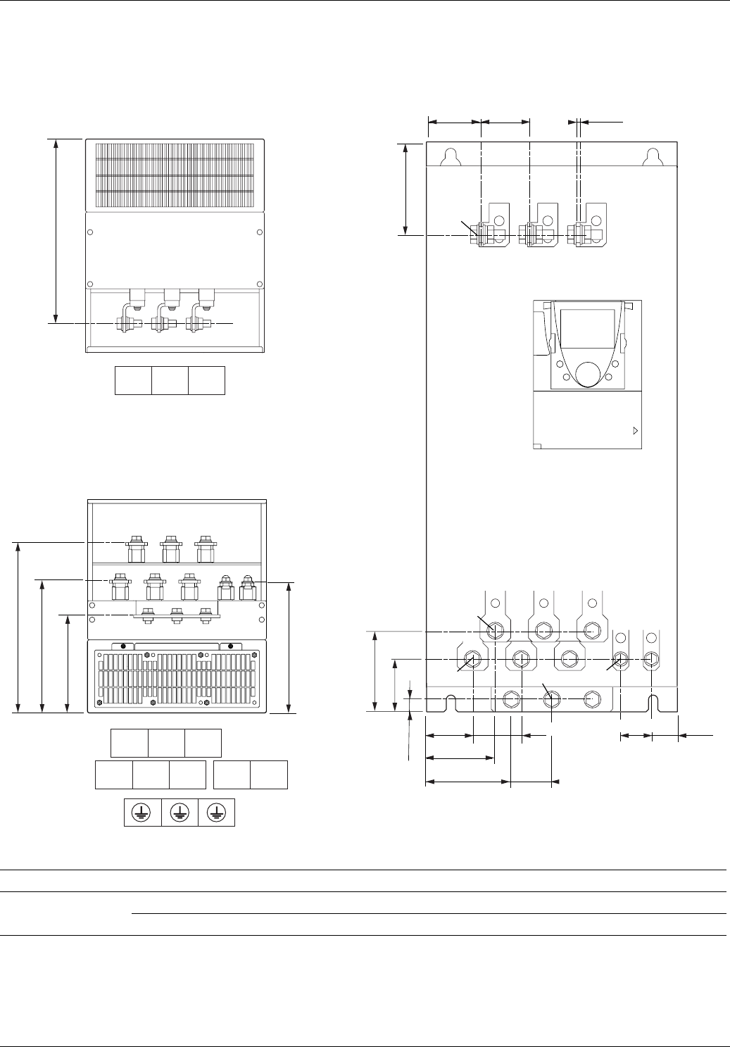
Layout of the ATV 61 power terminals and tightening torque
ATV61H D55M3X, D75M3X, D90N4, C11N4
Maximum terminal wire size/tightening torque
Drive terminals L1/R, L2/S, L3/T, U/T1, V/T2, W/T3 PC/-, PO, PA/+ PA, PB
2 x 100 mm
2
/24 Nm 2 x 100 mm
2
/41Nm 60 mm
2
/12 Nm
2 x 250 MCM/212 lb.in 2 x 250 MCM/360 lb.in 250 MCM/106 lb.in
PC/-PA/+PO
320 (12.54)
295 (11.55)
230 (9.01)
172 (6.74)
PA PB
U/T1 V/T2
R/L1
W/T3
S/L2 T/L3
225 (8.81)
115 (4.50)
70 (2.74) 60 (2.35)
100 (3.92)
65 (2.55)
14 (0.55)
32 (1.25)
50 (1.96)
105(4.11)
85(3.33)
38 (1.49)57(2.23)
60(2.35)
5 (0.2)
M10
M10
M8
M10
M12
View from below
View from above
Front view


