


35
2. Drive implementation
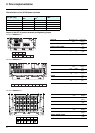
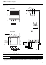
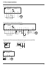
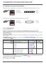
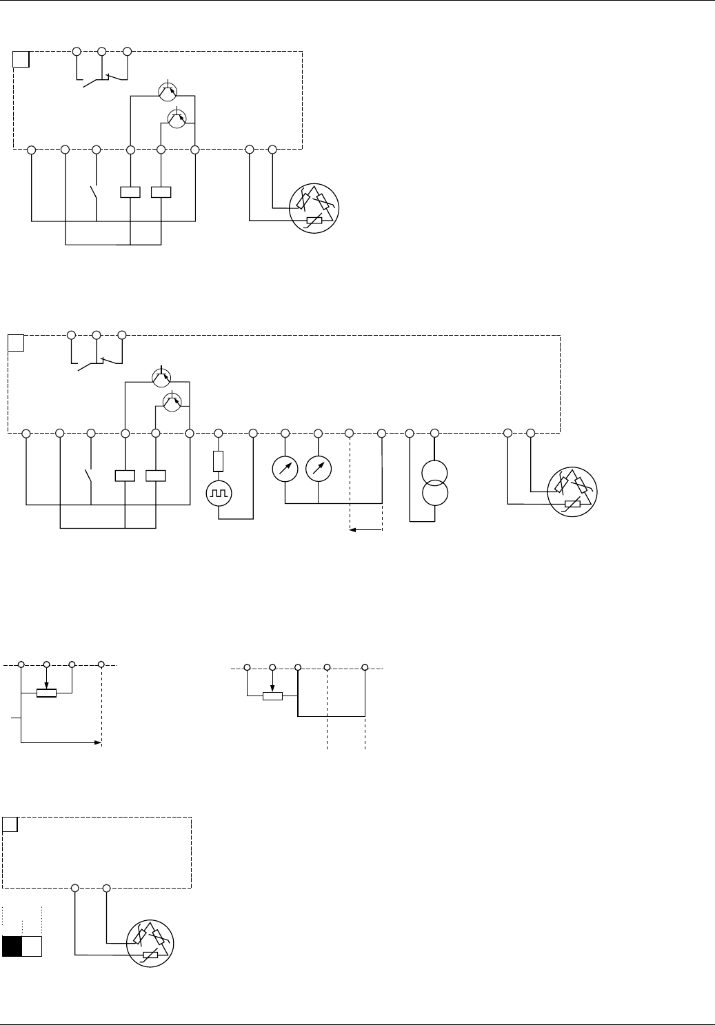
Connection diagram for logic I/O option card (VW3 A3 201)
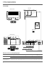
Connection diagram for extended I/O option card (VW3 A3 202)
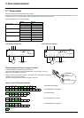
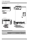
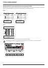
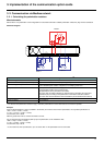
AI1 input on the ATV 61 wired as non differential 0-10 V (same as AI1 on the ATV38)
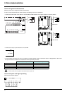
LI6 wired as PTC probe
+24
VW3A3201
CLO
LO2
LO1
LI7
0V
TH1+
TH1-
R3A
R3C
R3B
A1
Motor
+24
VW3A3202
0V
RP
CLO
LO4
LO3
LI11
0V
TH2+
TH2-
AO2
AO3
COM
AI4
AI3-
AI3+
R4A
R4C
R4B
A1
Source
0-20 mA
4-20 mA
X-Y mA
Motor
0 ± 10 V
or
X-Y mA
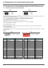
COM
Al 1
AI2
+ 10
+10
AI1+
AI2
AI1-
COM
ATV 38
ATV61
Reference
potentiometer
X-Y mA
Reference
potentiometer
0V
LI6
A1
ATV61Hppppp
PTC
LI
SW2
Motor