


72
3. Implementation of the communication option cards
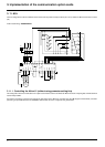
3. 11. 2. 4-speed mode, 2 directions of operation
Assignment of inputs/outputs
4 logic inputs used on the terminals, 2-wire control
LI1: Forward
LI2: Reverse
LI3: 2 preset speeds
LI4: 4 preset speeds
3. 11. 3. Managing the terminal outputs (AS-i monitoring bits)
3. 11. 4. Limitations
The commands transmitted by the data bits on the AS-i bus, which cannot be reproduced by means of direct wiring, are:
• Fast stop (0 1 0 0)
• Stop with DC injection (1 0 0 0)
• Freewheel stop (1 1 0 0)
• Fault reset (1 1 1 1)
In fact, it is not possible to wire directly, for example, bit D2 (0 1 0 0 = fast stop) on an additional logic input of the Altivar 61 and assign to
it the fast stop function, because each time bit D2 is at 1 but for another command (e.g., 0 1 0 1 = forward - SP2), the motor is stopped
because the stop function has priority.
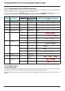
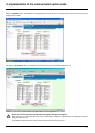
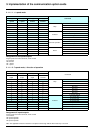
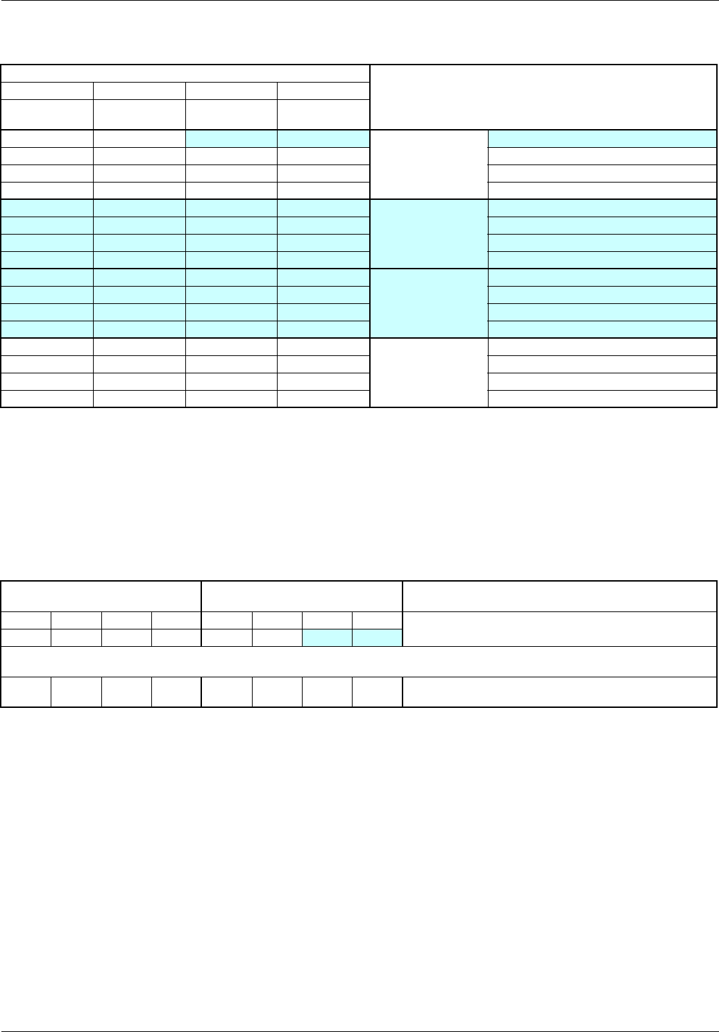
3. 11. 5. Configuring the drive logic I/O
Please refer to the Programming Guide for information about customizing Lix and Rx assignment.
Control bits
Command
D3(O) D2(O) D1(O) D0(O)
LI4
4-spd
LI3
2-spd
LI2
Reverse
LI1
Forward
00
0 0
Stop
Normal
0100
1000
1100
0 0 0 1
Forward
1
st
speed: LSP+AI
0 1 0 1 2
nd
speed: SP2
1 0 0 1 3
rd
speed: SP3
1 1 0 1 4
th
speed: HSP
0 0 1 0
Reverse operation
1
st
speed: LSP+AI
0 1 1 0 2
nd
speed: SP2
1 0 1 0 3
rd
speed: SP3
1 1 1 0 4
th
speed: HSP
0011
Reset
0111
1011
1111
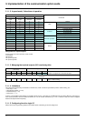
Mode parameterization bits
(not used)
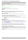
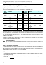
Monitoring bits Command
P3 P2 P1 P0 D3(I) D2(I) D1(I) D0(1)
Names of the AS-i variables
Example of assignment to the terminal relays
xxxx
R2 R1
Example 1:
11
D0(I)=1: drive ready for remote control
D1(I)=1: motor running