40
3. Implementation of the communication option cards
3. 2. 2. Reminder of the various connection methods:
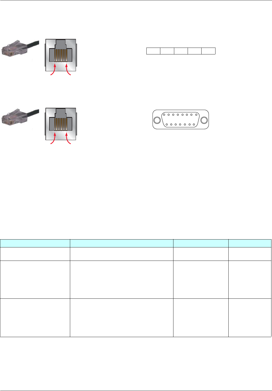
ATV 61 RJ45 connector on TSXSCA50 or other screw terminals: Use cable VW3 A8 306 D30 (RJ45 to stripped end, 3 meters)
ATV 61 RJ45 connector on TSXSCA62: Use cable VW3 A8 306 (RJ45 to 15-way Sub-D)
3. 2. 2. 1. Configuring the drive
There are two possible scenarios.
Scenario 1 Using the built-in port when replacing the VW3A58303 Modbus/Unitelway option card
As the PowerSuite software workshop is not able to anticipate this scenario, the communication, address and protocol-format parameters
must be entered manually:
Configuring the address
Transfer the Altivar 38 parameters to the Altivar 61 using the integrated display terminal, the graphic display terminal or the PowerSuite
software workshop:
The configuration of the Modbus network parameters can be accessed via the
[MODBUS NETWORK] (MdI-) submenu in the [1.9
- COMMUNICATION]
(COM-) menu.
Configuring the drive control mode
Check and configure the control mode applied to the drive in the [1.6 - COMMAND] (CtL-) menu on the graphic display terminal, the
integrated display terminal or the PowerSuite software workshop.
[Profile] (CHCF) = [8 serie] (SE8)
2 = 0 V - brown
t
0VL 0VL D(A) D(B) 2 = 0 V
3 = D_B - blue 12345 4 = D_A
5 = D_A - white/blue 5 = D_B
2 = 0 V - brown 15 = 0 V
3 = D_B - blue 14 = D_A
5 = D_A - white/blue 7 = D_B
Modbus parameter Description/Possible values Terminal display Default value
[Modbus Address] (Add) 1 to 247
Drive Modbus disabled (0)
[1] (1) to [247] (247) [Off] (OFF)
[Modbus baud rate] (tbr) 4800 bps
9600 bps
19200 bps
38400 bps
[4.8 Kbps] (48)
[9.6 Kbps] (96)
[19.2 Kbps] (192)
[38.4 Kbps] (384)
[19200] (192)
[Modbus format] (tFO) 8 data bits, odd parity, 1 stop bit
8 data bits, even parity, 1 stop bit
8 data bits, no parity, 1 stop bit
8 data bits, no parity, 2 stop bits
[8-0-1] (8o1)
[8-E-1] (8E1)
[8-N-1] (8n1)
[8-N-2] (8n2)
[8 E 1] (8E1)
8........................1
8........................1
1
2
3
4
56
7
8
1514131211109


