


34
2. Drive implementation
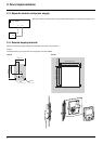
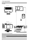
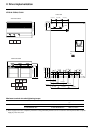
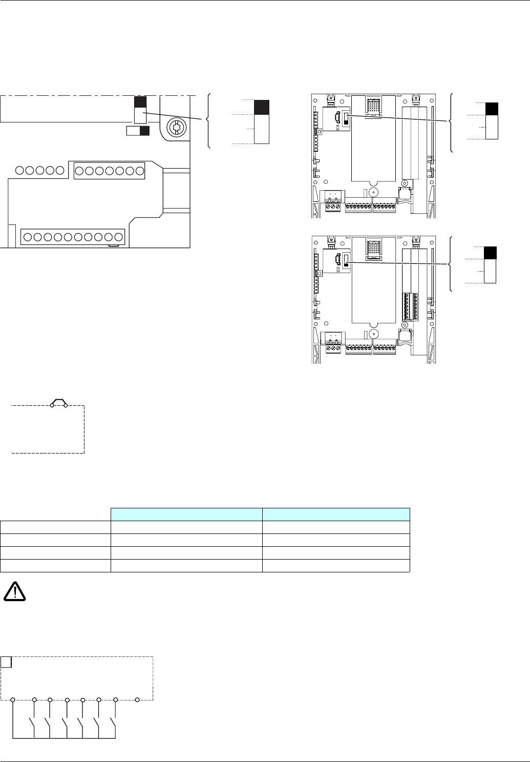
Control wiring and I/O characteristics
(Warning: Check the I/O assignment made by PowerSuite)
In order to ensure that the Altivar 61 works correctly, the following rules must be adhered to:
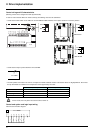
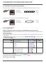
• Check that the SW1 switch on the Altivar 61 and the SW3 and SW4 switches on the option cards are in "Source" position.
• Check that the strap is present between +24 and PWR.
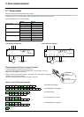
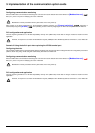
• The PTC probes connected on an ATV 61 correspond to market standards. Please note that the values are slightly different. Check that
the trip thresholds are suitable for the temperature levels supported by the motor.
In PTC mode, Li6 is only taken into account after a Power on.
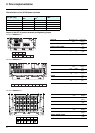
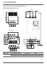
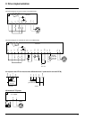
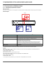
Control and option card logic input wiring
Control card connection diagram
ATV38 value (kOhms) ATV 61 value (kOhms)
Probe short-circuit 0.200 < 0.05
Reset 1.5 1.8
Overheating 2 3
Probe break 20 > 100
R1B
R1A
R1C
R2A
R2C
AI1+
+10
AI1-
COM
AI2
COM
AO1
0V
P24
LI1
LI2
LI3
LI4
LI5
LI6
+24
PWR
RJ45
SW1
SW2
Ext
Source
Sink
Int
SW3
Ext
Source
Sink
Int
SW4
Ext
Source
Sink
Int
VW3 A3 201
VW3 A3 202
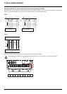
ATV71HpppM3
PWR
+24
A1
ATV71Hppppp
LI1
LI5
+24
0V
LI3
LI2
LI6
LI4