


Digital Dosing Units
20
Section 3: Initial Installation and Operation
3.1 Initial Installation
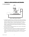
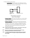
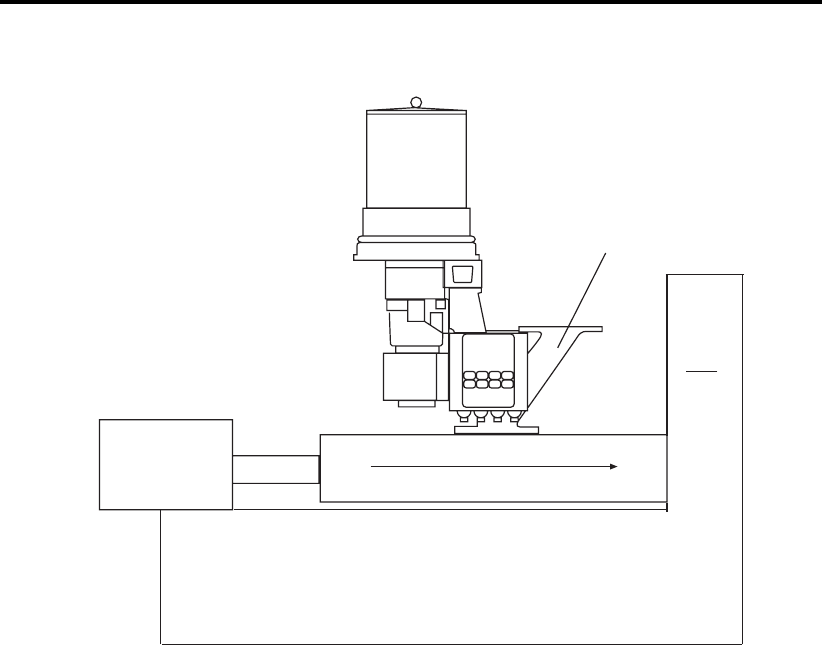
Direction of Material Flow
Hopper Piece
Processing
Machine
Figure 4. Digital Dosing Unit Assembly
1. The Digital Dosing additive feeder is not affected by machine vibration, therefore best
performance is achieved by mounting the unit directly to the feed throat of the molding
machine or extruder (see Figure 4). The inlet into the process machine must be
greater than 2” diameter; otherwise, an adapter might be necessary. If an adapter is
necessary, it must be designed so that there are no edges where material can be
trapped. The adapter must be smooth to promote even material flow. Consult factory
for any special requirements.
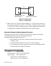
2. Optimum mounting of the Digital Dosing feeder is shown in Figure 4, with the additive
being dosed on the first screw flights.
3. The controller can be mounted on either side of the blender base to optimize operator
interface. An optional remote mounting kit for the controller is available from the
manufacturer to relocate the controller closer to the operator. The control unit must not
be exposed to extreme heat (maximum temperature 45°C or 115°F) or excessive
moisture.