


Digital Dosing Units
8
Section 2: Quick Start-up
Quick Start is intended to help you in starting up your Digital Dosing feeder quickly
and easily. Please refer to the manual to go into greater detail.
Unpacking:
1. Unpack box, making sure all parts indicated on packing list are included.
2. Check all parts and equipment for any damage sustained during shipment.
3. If any damage is noted, contact manufacturer for replacement or service.
4. Make sure the following are present before proceeding:
; Power source 110 or 220 volt, single phase, 50 or 60 hertz (verify voltage on
Serial Number tag
; Proper mounting flange adapter for the feed throat
; Dry (ZERO VOLTAGE) contact that closes during screw recovery of IMM
; Gram scale to measure weight of additive material for calibration.
Mounting:
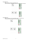
1. Mount the complete unit, including dosing hopper full of material, on the feed throat
(may need an adapter for feed throat).
2. Identify the motor drive connector (“Amp” connector-black) and connect to motor.
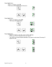
3. Identify the communication cable (DB-9 plug-silver) and connect to DB-9 connector
under motor drive assembly.
4. Identify power cord and plug into appropriate outlet.
5. INJECTION MOLDING: Identify the cycle/run cable (2-conductor cable-gray) for
connection to a dry (ZERO VOLTAGE) contact that closes during the screw recovery
cycle of the molding machine.
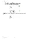
6. EXTRUSION: Identify the input cable (2-conductor cable-gray) for connection to 0-10
VDC or 0-20 mA signal that indicates speed (rpm) of the extruder.