


Digital Dosing Units
22
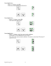
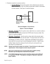
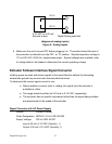
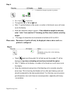
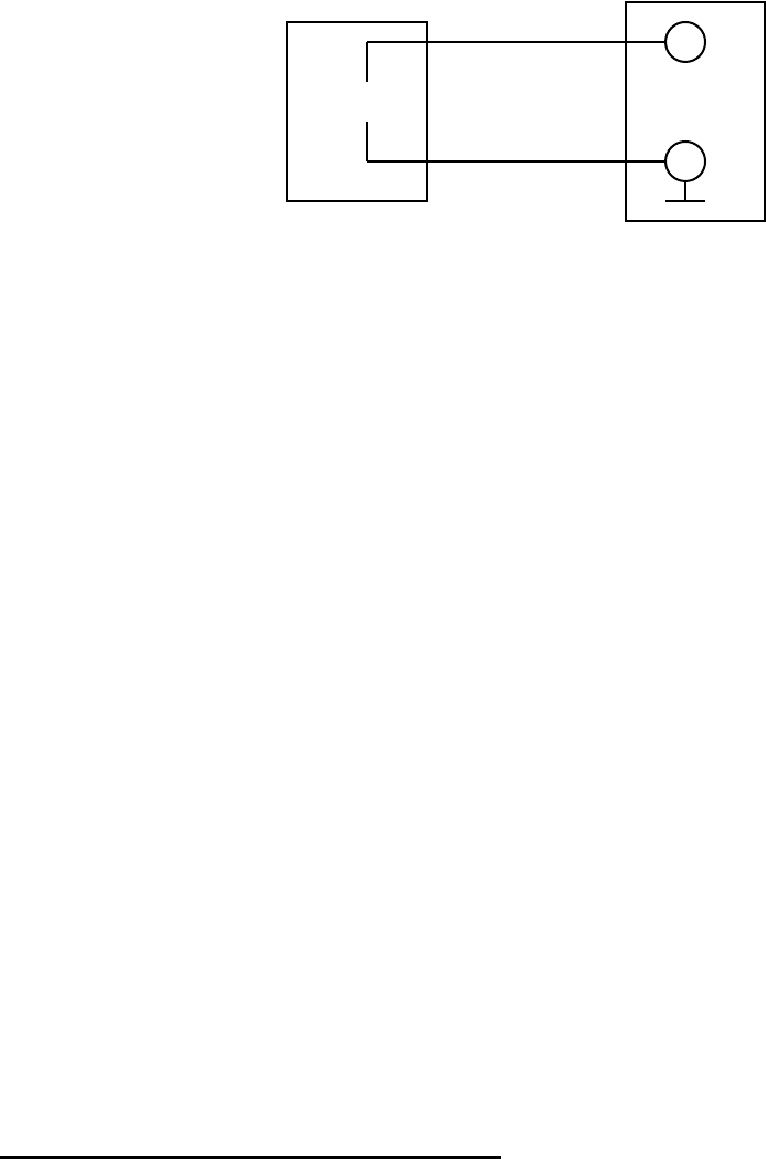
J12-4 _
J12-3 +
0-10 VDC or 0-20 mA
Extruder output Digital Dosing controller
(diagram of analog inputs)
Figure 6. Analog Inputs
5. Make sure the unit is turned OFF before plugging it in. The switch toward the rear of
the controller unit should be in the OFF, or “O” position. Standard operation voltage is
110 or 220 VAC, 50/60 Hz, single-phase power. Special voltages are available, refer
to voltage label on the feeder to determine the correct operating voltage.
Extruder Follower Interface Signal Converter
Isolating power sources and sensor signals is the most effective method for eliminating
undesirable ground loop currents and induced electrical noise.
To determine the correct signal convert to use:
o Define whether a current (mA) or voltage (dc) signal from the extruder is
available to utilize.
o The range should be either be 0-20 mA or 0-10 VDC, respectively.
o The controller has no specific requirement other than the signal being isolated
and proportional to the speed of the extruder.
Signal Converter with AC Power Supply
Vendor: Phoenix Contact
Order Designation: MCR-FL-C-UI-UI-DCI-24/230
Supply Voltage: 20V to 253V AC/DC
Input 4-20 mA, 0-10 VDC (Quantity: 1)
Output 0-20 mA, 0-10 VDC (Quantity: 1)