


Digital Dosing Units
44
4.4 Optional Equipment, Level Switches and Communications
Options
Optional equipment for the Digital Dosing Additive Feeder includes:
Alarms
Several alarm options are available for the Digital Dosing feeder. The standard unit comes
with a flashing alarm symbol on the faceplate. Options include both audible horns and
flashing lights. An optional no voltage alarm relay can be connected to the user’s central
alarm system.
Level switches (probes)
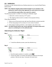
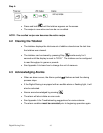
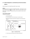
To adjust the level switches:
1. Turn the controller ON.
2. Fill the dosing station until the level sensor is one-third covered.
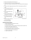
3. Remove the small plastic screw (M3) on the back of the level sensor (see
Figure 7).
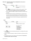
LED Yellow (Station)
on: Station Filled
off: Station Emptied
LED Green (Level Probe)
on: Power Supply Available
off: Power Supply Not Available
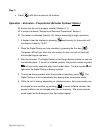
Trim-pot with
Plastic Screw M3
Cable
Blind Lid
Protective Screw
npn: Normally Closed
pnp: Normally Open
10
npn: Normally Open
pnp: Normally Closed
Level Probe
Figure 7. Level Sensor Screw
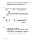
4. Turn the trim-pot until the yellow control lamp just switches off.