Digital Dosing Units
5
1.1 Controller
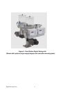
The Digital Dosing additive feeder consists of a controller(s), dosing motor(s), and feeder(s).
The controller is used to:
• Configure the unit to the desired process.
• Calibrate the feeder
• Run, monitor, and stop the dosing process
• Enter, recall, and run recipes
• Troubleshoot problems via error codes
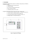
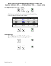
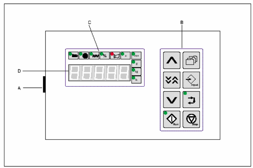
A keypad and LED display (see Figure 3) are used to enter, or change, data.
• The control system is switched on (position “1") with the On/Off switch. (A)
• The control system is operated through the keypad. (B)
• The individual operating modes are indicated by symbols. (C)
• Messages appear on a 5-digit LED display. (D)
Figure 3. Keypad and LED Display


