


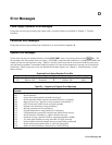
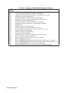


116 Digital Port Functions
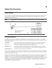
Digital I/O Operation
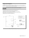
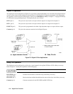
The digital port can be configured (see Figure F-4) to provide a digital input/output to be used with custom digital interface
circuits or relay circuits. Some examples are shown Figure F-5. See Figure F-1 for the pin assignments of the mating plug
and Appendix A for the electrical characteristics of the port. See DIG:DATA[:VAL] in “Chapter 7 - Language Dictionary"
for information on programming the port. The digital port pins are as follows:
OUT 0 (pin 1)
This port can only be used as an open-collector output. It is assigned a bit weight of 1.
OUT 1 (pin 2)
This port can only be used as an open-collector output. It is assigned a bit weight of 2.
IN/OUT 2 (pin 3)
This port can be programmed to be either a high impedance input or an open-collector output.
Common (pin 4)
This pin is the common connection for the Digital I/O ports.
Figure F-5. Digital l/O Port Applications
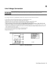
Relay Link Operation
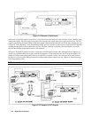
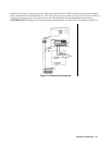
The digital port can be configured to provide relay control outputs for the Agilent 59510A or 59511A Relay Accessory.
Refer to Figure F-1 for the pin assignments of the mating plug.
Not used with units that output more than 50 amps.
RLY SEND (pin 1)
(pin 2 is not used)
Provides the serial data to control the relays in the Relay Accessory.
RLY RTN (pin 3)
Receives the data readback that indicates the status of the relays in the Relay Accessory.
Common (pin 4)
Common connection for the RLY SEND and RLY RTN lines.