


User Connections
34
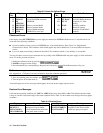
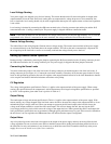
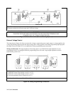
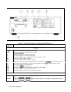
Load Connection ô Analog Connector í Load
÷ Program each unit for full load current and 1/2 the load voltage
Connect for remote sensing (optional)
WARNING
FLOATING VOLTAGES MUST NOT EXCEED
±
240 VDC NO OUTPUT TERMINAL MAY
BE MORE THAN 240 V FROM CHASSIS GROUND.
Figure 4-8. Series Connection (Remote Sensing Optional)
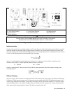
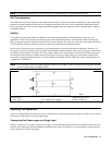
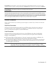
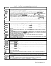
External Voltage Control
The setup shown in Figure 4-9 allows an external dc voltage to program the power supply output. A voltage applied to the
voltage programming input programs the output voltage and a voltage applied to the current programming input programs
the output current. See Figure 4-1 for an explanation of these programming input connections.
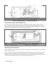
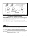
Wiring Considerations. The input impedance of the analog input is over 30 k
Ω
. If the output impedance of your
programming source is not negligible with this, programming errors will result. Larger output impedances result in
proportionally greater errors.
1 Voltage programming source 0 to –4.15V
2 Differential current programming source 0 to +6.75 V
3 Differential current programming source 0 to –6.75 V
4 Current programming source (floating) 0 to 6.75 V
* Maximum Potential between –IP and ↓P is ±15 V
Figure 4-9. Analog Programming Connections