


Remote Programming 55
Note The last query string can be handled without difficulty. However, should you request too many queries,
the system may return a "Query DEADLOCKED” error (-430). In that case, break the long string into
smaller parts.
Programming the Digital I/O Port
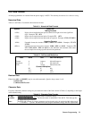
Digital control ports 1 and 2 are TTL outputs that can be programmed either high or low. Control port 3 can be
programmed to be either a TTL input or a TTL output. Send a decimal parameter that translates into the desired straight
binary code for these ports. (See DIG:DATA[:VAL] in "Chapter 3 - Language Dictionary" for the port bit configurations.)
DIG:DATA 3 Set ports 1 and 2 high and make 3 another output port.
DIG:DATA 7 Set ports 1 and 2 high and make 3 an input port.
DIG:DATA? Read back the present port configuration.
System Considerations
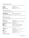
The remainder of this chapter addresses some system issues concerning programming. These are power supply addressing
and the use of the following types of GPIB system interfaces:
1. HP Vectra PC controller with Agilent 82335A GPIB Interface Command Library.
2. IBM PC controller with National Instruments GPIB-PCII Interface/Handler.
3. Agilent controller with Agilent BASIC Language System.
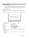
Setting the GPIB Address
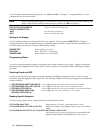
The power supply address cannot be set remotely; it must be set from the front panel. Once the address is set, you can
assign it inside programs. Figure 4-10 shows the ways the power supply can be connected to the GPIB bus. You can set up
the GPIB address in one of three ways:
1. As a stand-alone unit (the only unit at the address). It has a primary address in the range of 0 to 30. For example:
5 or 7
2. As the direct unit in a serial link. It is the only unit connected directly to the GPIB bus. The primary address is unique
and can be from 0 to 30. It is entered as an integer followed by a decimal separator. The secondary address always is
0, which may be added after the primary address. If the secondary address is omitted, it is assumed to be 0. For
example:
5.0 or 7.
3. As a linked unit in serial link. It gets its primary address from the direct unit. It has a unique secondary address that
can be from 1 to 15. It is entered as an integer preceded by a decimal separator. For example:
.1 or .12
When you enter a secondary address, leading zeros between the decimal separator and the first digit are ignored. For
example, .1, .01, and .001 are accepted as secondary address 1 and displayed as 0.01. Zeros following a digit are not
ignored. Thus, .10 and .010 are both accepted as secondary address 10 and displayed as 0. 10.
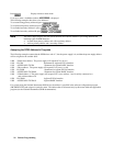
Changing the Power supply GPIB Address
Use the key and numerical keypad for entering addresses. The power supply is shipped with a 5 stand-alone
address as the default. The general procedure for setting an address is:
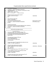
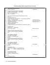
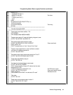
Action Display Shows
Press
Current address
Press new address keys New address replaces numbers on the display