


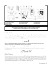

User Connections 33
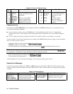
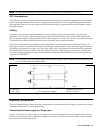
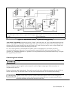
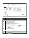
Analog Connector ô Slave Unit í Master Unit
÷Program only the master. Set slave output and OVP slightly higher than the master to ensure that slave stays in CC mode
û Load
ø Load Connection
Only local sensing permitted
Connect for optional remote sensing
Figure 4-7. Auto-Parallel Connection (Remote Sensing Optional)
Auto-Parallel Programming. Program only the first ("master") unit in the series; the "slave" units automatically track the
master’s output. However, the voltage and OVP settings of the slave units must be set higher than the operating voltage of
the master unit. This ensures that the slave units will operate in CC mode. Functions such as status, voltage readback, and
current readback can still be read back individually for each unit.
If a "slave" unit experiences a desired shutdown condition (such as overtemperature or overcurrent), it will not
automatically shut down all other units. You must first enable remote inhibit (RI) and discrete fault indicator (DFI)
operation. See "Fault/Inhibit Operation" in Appendix F for wiring information and "Questionable Status Group" in Chapter
8 for programming information.
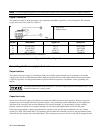
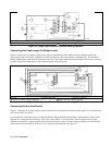
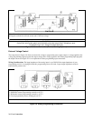
Connecting Units in Series
Floating voltages must not exceed 240 Vdc. No output terminal may be more than 240 V from chassis
ground.
Figure 4-8 shows how power supplies can be connected in series for higher voltage output. Series connections are
straightforward in this case.
Program each power supply independently. If two units are used in the series configuration, program each unit for 50% of
the total output voltage. Set the current limit of each unit to the maximum that the load can handle without damage.
Each power supply has a reverse voltage protection diode across its output. If a reverse voltage is
applied, the unit cannot control the current conducted through this diode. To avoid damaging the
unit, never connect it in such a way that a reverse voltage can force it to conduct current in excess
of the unit’s maximum reverse diode current (see Table A-2).