


Front Panel Operation 39
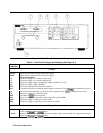
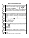
Table 5-1. Front Panel Controls and Indicators (continued)
í SYSTEM Keys
When the power supply is under remote control, press to enable local operation. This control can be
defeated by a lock-out command over the GPIB
Press to display the power supply’s GPIB address. You can change the address with the ENTRY keys
Use to display error codes generated during remote operation. (Select by pressing .)
Use to restore a previously saved power supply state. Use ENTRY keys through to specify which
location to recall. (Select by pressing
.)
Note: Location 0 may contain the power supply turn-on state. See "Turn-on operation" in this chapter.
Use to save the power supply’s present state to nonvolatile memory. (Select by pressing
.) Use
ENTRY keys to specify the location where you want to store the state. Use locations
through .
This unlabeled blue key is the Shift key. Press to access the shifted (alternate) key functions.
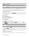
÷ Function Keys
Press to enable or disable the power supply output. This key toggles between the two states. The disabled
state programs the output to the *RST voltage and current settings.
Press to display the output voltage setting. After pressing , you may use the ENTRY keys to change
the value.
Press to display the output current setting. After pressing , you may use the ENTRY keys to change
the value.
Press to display the OV trip voltage setting. After pressing , you may use the ENTRY keys to change
the value.
When the Prot annunciator is on, press to see which protection circuit caused the power supply to
shut down. Response can be OC (overcurrent), OT (overtemperature), or OV (overvoltage). If no protection
circuit has tripped, the display will show dashes (- - - -).
Press this key to reset the protection circuit. If the condition that caused the circuit to trip has been
removed, the Prot annunciator will go off.
Press to enable or disable the power supply OCP trip circuit. This key toggles between the two states. which
are indicated by the OCP annunciator.
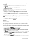
û ENTRY Keys
Press to increment the output voltage in the CV mode, or to increase the voltage setting after you have
pressed the
key.
3
Press to decrement the output voltage in the CV mode, or to decrease the voltage setting after you have
pressed the
key.
3
Press to increment the output current in the CC mode, or to increase the current setting after you have
pressed the
key.
3
Press to decrement the output current in the CC mode, or to decrease the current setting after you have
pressed the
key.
3
-
Press to select numerical values.
Press to enter a minus sign.
Press to delete the last keypad entry. Use this key to remove one or more incorrect digits before they are
entered.
3
These four entry keys operate in two modes. Press and release for a single minimal change as determined
by the programming resolution (see Table A-2). Press and hold for an increasingly rapid output change.
Press to delete an entire keypad entry and return to the meter mode. Use this key to exit from a value before
it is entered.
Press to enter a value or to accept an existing value and return the display to the meter mode.
The remaining shifted keys are for calibration (see Appendix B - "Calibration").