


User Connections 27
4
User Connections
Rear Panel Connections
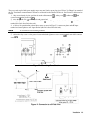
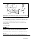
Make application load connections to the output terminals or bus bars, analog connector, and digital connector as shown on
the rear-panel drawing for your model power supply. Make controller connections (GPIB and serial link) as shown in Figure
4-6 at the end of this chapter.
Load Wire Selection
Fire Hazard To satisfy safety requirements, load wires must be large enough not to overheat when
carrying the maximum short-circuit current of the power supply. If there is more than one load, then
any pair of load wires must be capable of safely carrying the full-rated current of the unit.
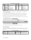
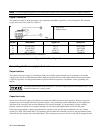
Table 4-1 lists the characteristics of AWG (American Wire Gauge) copper wire.
Table 4-1. Stranded Copper Wire Capacity and Resistance
AWG Ampacity
l
Resistance
2
AWG Ampacity
1
Resistance
2
No.
(Ω/m)
No.
(Ω/m)
14 25 0.0103 8 60 0.0025
12 30 0.0065 6 80 0.0016
10 40 0.0041 4 105 0.0010
NOTES:
1. Ampacity is based on 30 °C ambient temperature with conductor rated at 60 °C. For ambient temperature other
than 30 °C, multiply the above ampacities by the following constants:
Temp (°C) Constant
Temp (°C) Constant
21-25 1.08 41-45 0.71
26-30 1.00 46-50 0.58
31-35 0.91 51-55 0.41
36-40 0.82
2. Resistance is nominal at 75 °C wire temperature.
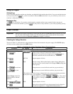
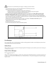
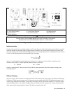
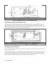
Analog Connector
This connector, which is on the rear panel, is for connecting remote sense leads, external current monitors, and external
programming sources. The connector accepts wires sizes from AWG 22 to AWG 12.
Insert Wires
ô Tighten Screws
IM Current monitor output.
VP Voltage programming input.
+IP Differential current programming input.
–IP Differential current programming input.
↓P Common for VP and IM signals (referenced to +OUT).
+S + remote sense input.
–S –remote sense input.
Figure 4-1. Rear Panel Analog Connector