


User Connections 35
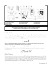
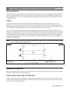
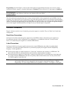
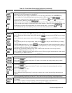
Programming. Note from Figure 4-1 that you have three options for programming the current. You can use a voltage
source that is positive, negative, or floating with respect to Common P. Do not exceed
±
15 V with respect to Common P.
Make certain that the common connection for your voltage programming source is isolated from the
load. Failure to do this may cause damage to the power supply.
The effect of the analog programming source is always summed with the values programmed over the GPIB or from the
front panel. The voltage source can act alone only if you set the other program sources to zero. Keep the total programmed
setting of the unit (the analog input summed with the GPIB or front panel settings) at or under the output ratings specified in
Table A-2. Exceeding the output ratings will not damage the unit, but it may not be able to regulate its output at the higher
levels. If this happens, the Unr annunciator will light to warn you that the output is unregulated.
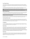
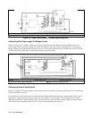
Controller Connections
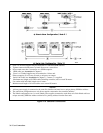
Figure 4-10 shows two basic ways of connecting your power supply to a controller. They are "linked" and "stand-alone
configurations.
Stand-Alone Connections
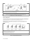
See Figure 4-10A. Each stand-alone power supply has its own GPIB bus address. Stand-alone power supplies may
be connected to the bus in series configuration, star configuration, or a combination of the two. You may connect
from 1 to 15 stand-alone power supplies to a controller GPIB interface.
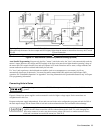
Linked Connections
See Figure 4-10B. Up to 16 power supplies may be used at a single GPIB primary bus address by making linked
connections. (You cannot use linked connections if you intend to program power supplies with the Compatibility
Language - see the Appendix G.)
■ The first power supply in a linked connection is a "direct unit" connected to the controller via a GPIB cable. The
direct unit is the only unit connected directly to the bus and has a unique primary bus address.
■ The remaining power supplies are "linked units” connected to the direct unit via a serial-link cable. Each linked unit
has a unique secondary GPIB address and derives its primary address from the direct unit. You may connect from 1
to 15 linked supplies to each direct unit.
Note The power supply is shipped from the factory with its GPIB address set to 5. The power supply primary
and secondary addresses can be changed from the front panel as described in Chapter 6 - "Remote
Programming". For power supply GPIB interface capabilities, see Table 1-5 in Chapter 1 of this guide.