


Front Panel Operation 43
Saving and Recalling Operating States
You can save programming time by storing up to 5 operating states in nonvolatile memory. The front panel programming
parameters that are saved are:
■ Output voltage, Output current, *OVP voltage,
■ OCP state (on or off), Output state (enabled or disabled).
Note More power supply parameters are saved in remote operation. See Chapter 7.
As an example, set up the following state:
■ Voltage = 45 V Current = 5 A OVP voltage = 48 V.
■ OCP = on (OCP annunciator on) Output = off (Dis annunciator on).
Save the above state to location 1 by pressing
. Now set up the following state:
■ Voltage = 50 V Current = 2.5 A OVP voltage = 55 V.
■ OCP = off (OCP annunciator off) Output = on (Dis annunciator off).
Save the above state to location 2 by pressing
.
Restore the first state by pressing
and verify the parameters. Restore the second state by pressing
. Note how the power supply is automatically programmed each time.
Turn-On Conditions
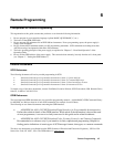
Whenever you apply power to a new power supply it automatically turns on in a safe reset state with the following
parameters:
off 0 minimum*
maximum off
*Minimum is the *RST value specified in Table A-2.
It is recommended that you leave the turn-on conditions as programmed. However, you may change them. To do this:
1. Set up the power supply to the state you want when it is turned on.
2. Store that state to location 0.
3. Turn off the power supply.
4. Hold in the
key and turn the power supply back on. The display indicates RCL 0 PWR-ON to verify that the
power supply has configured its turn-on state to that stored in location 0.
5. From now on the unit will always turn on to the state defined in location 0.
To return the power supply to the original factory reset state, hold down the
key when you turn on the unit. The display
indicates RST POWER-ON to verify that the power supply has configured its turn-on state to the original reset state. From
now on it will continue to turn on in that state.
Setting The GPIB Address
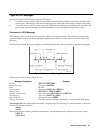
Types of Power supply GPIB Addresses
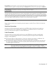
Figure 4-8 in Chapter 4 shows the ways the power supply can be connected to the GPIB bus. You can set up the GPIB
address in one of three ways: