


User Connections 31
Note The signal ground binding post on the rear panel is a convenient place to ground the sense shield.
OVP Considerations
The OVP circuit senses the voltage near the output terminals and not at the sense terminals. Depending on the voltage drop
between the output terminals and the load, the voltage sensed by the OVP circuit can be significantly higher than actually
being regulated at the load. You must program the OVP trip high enough to compensate for the expected higher voltage at
the output terminals.
Stability
Using remote sensing under unusual combinations of load-lead lengths and large load capacitances may cause your
application to form a low-pass filter that becomes part of the voltage feedback loop. The extra phase shift created by this
filter can degrade the unit’s stability and result in poor transient response. In severe cases, this may cause output oscillations.
To minimize this possibility, keep the load leads as short as possible and tie wrap them together.
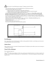
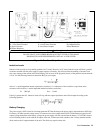
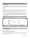
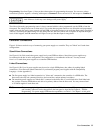
In most cases, following the above guidelines will prevent problems associated with load lead inductance. However, if a
large bypass capacitor is required at the load and load-lead length cannot be reduced, then a sense-lead bypass network may
be needed to ensure stability (see Figure 4-4). The voltage rating of the 33
µ
F capacitors should be about 50% greater than
the anticipated load-lead drop. Addition of the 20-
Ω
resistors will cause a slight voltage rise at the remote sensing points.
For utmost voltage programming accuracy, the unit should be recalibrated with the DVM at the remote sensing points (see
“Appendix B - Calibration”).
Note If you need help in solving a stability problem with the power supply, contact an Agilent Service Engineer through
your local Agilent Sales and Support Office.
Load Leads ôRemote Sense Points
Cl, C2 = 33
µ
F
C3 = Load bypass capacitor
R1, R2 = 20
Ω
, 1%
Figure 4-4. Sense Lead Bypass Network
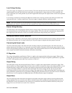
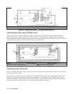
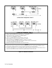
Operating Configurations
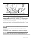
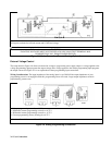
Figures 4-5 through Figure 4-8 show the various configurations for connecting to the load. Figure 4-9 shows how to connect
an external voltage source for analog programming.
Connecting One Power supply to a Single Load
Figure 4-5 shows how to connect a single power supply to one load. Keep output load leads close together (small loop area)
to obtain a low inductance and low impedance connection to the load. If you wish to use remote sensing, connect the sense
leads at the load as shown in the figures.