


User Connections
32
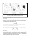
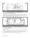
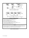
Load Connection ôLoad íAnalog Connector
Connect for remote sensing (optional) Connect for local sensing (default)
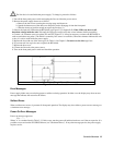
Figure 4-5. Single Load Connection (Remote Sensing Optional)
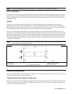
Connecting One Power supply To Multiple Loads
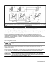
Figure 4-6 shows how to connect a single power supply to more than one load. When connecting multiple loads to the
power supply with local sensing, connect each load to the output bus bars with separate connecting wires. This minimizes
mutual coupling effects and takes full advantage of the unit’s low output impedance. Keep each pair of load wires as short as
possible and twist or bundle them to reduce lead inductance and noise pickup.
Loads ôLoad Connection íAnalog Connector
Connect for remote sensing (optional) Connect for local sensing (default)
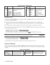
Figure 4-6. Multiple Load Connection (Remote Sensing Optional)
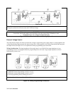
Connecting Units in Auto-Parallel
Figure 4-7 illustrates how power supplies can be connected in auto-parallel for increased current output. You can connect up
to five units of the same model.
Use load leads of a sufficient wire size so that the absolute voltage difference between the + output terminal of the "master"
unit and the + output terminal of the first "slave" unit is kept under 2 V at rated current. This also applies to the voltage
difference between the + output terminals of the first and second slave units. If remote sensing is required, connect the load
to the remote sense terminals of the master unit, as shown by the dashed lines in Figure 4-7.