


124 Index
connector
analog, 27
digital, 28
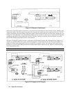
controller connections, 35
linked, 35
stand-alone, 35
conventions, 46
CRD, 51
current monitor resistor, 107
current programming, 41, 53
current sinking, 16
cv mode, 16, 42
—D—
damage, 17
description, 15
detecting SRQ events, 54
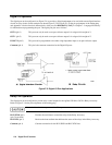
DFI descrete fault indicator, 90
digital connector, 17, 28, 115
digital I/O, 28
digital I/O programming, 55
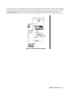
digital port configuration, 117
dimensions, 18
direct unit, 35, 43, 55
display
text, 54
DOS drivers, 57
downprogramming, 16
—E—
entry keys
←(backspace), 39
↑Current, 39
↑Voltage, 39
0 - 9, 39
equivalent series resistance, 29
error handling, 57
error messages
calibration, 102
checksum, 26
power-on, 25
runtime, 26
selftest, 25
system, 111
example programs, 57
external voltage control, 34
—F—
fan, 18
fault/inhibit, 28
FLT indicator, 90
FLT output, 115
front panel, 37
annunciators, 38
function keys
Current, 39
OCP, 39
Ouptut On/Off, 39
OV, 39
Prot Clear, 39
Protect, 39
Voltage, 39
fuse
location, 25
replacing, 25
—G—
ground, earth, 13
guide, user’s, 13
—H—
header, 49
long form, 49
short form, 49
history, 5
GPIB
capabilities, 46
command library for MS DOS, 45
controller programming, 45
references, 45
GPIB address, 24, 43, 55
assigning in programs, 56
changing, 44, 55
—I—
IM, 27
IN/OUT 2, 118
inductive loads, 29
INH common, 115
INH indicator, 90
INH input, 115
initial conditions, 40
input
connections, 18
power, 14
rating, 18
inspection, 17
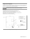
installation
VXIplug&play, 20
IP-, 27
IP+, 27
—L—
language dictionary, 63
line connections
3-phase, 18
line fuse, 18
line select switch, 113
line voltage conversion, 113
linked connections, 35
linked unit, 35, 43, 55
load, battery, 29
load, capacitive, 28