


Status Reporting
90
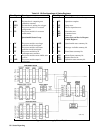
Status Byte Register
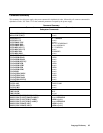
This register summarizes the information from all other status groups as defined in the "IEEE 488.2 Standard Digital
Interface for Programmable Instrumentation" standard. The bit configuration is shown in Table 8-1. The register can be
read either by a serial poll or by *STB?. Both methods return the same data, except for bit 6. Sending *STB? returns MSS
in bit 6, while poring the register returns RQS in bit 6.
The MSS Bit
This is a real-time (unlatched) summary of all Status Byte register bits that are enabled by the Service Request Enable
register. MSS is set whenever the power supply has at least one reason (and possibly more) for requesting service. Sending
*STB? reads the MSS in bit position 6 of the response. No bits of the Status Byte register are cleared by reading it.
The RQS Bit
Whenever the power supply requests service, it sets the SRQ interrupt line true and latches RQS into bit 6 of the Status Byte
register. When the controller services the interrupt, RQS is cleared inside the register and returned in bit position 6 of the
response. The remaining bits of the Status Byte register are not disturbed.
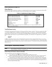
Output Queue
The Output Queue is a first-in, first-out (FIFO) data register that stores power supply-to-controller messages until the
controller reads them. Whenever the queue holds one or more bytes, it sets the MAV bit (4) of the Status Byte register. If
too many unread error messages are accumulated in the queue, a system error message is generated (see Table 9-1 in
"Chapter 9 - Error Messages"). The Output Queue is cleared at power on and by *CLS.
Service Request Enable Register
This register is a mask that determines which bits from the Status Byte register will be ORed to generate a service request
(SRQ). The register is programmed with the *SRE common command. When the register is cleared, no service requests
can be generated to the controller.
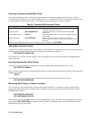
Inhibit/Fault Indicator
The remote inhibit (INH) and discrete fault (FLT) indicators are implemented through their respective INH and FLT
connections on the rear panel. Refer to Appendix F for more information.
RI (Remote Inhibit)
Whenever a remote inhibit signal is received at the digital port (see Appendix F - "Digital Port Functions" ), the power
supply will receive an RI event at the Questionable Status register. By programming the status subsystem, you may use RI
to generate a service request (SRQ) to the controller and/or to create a DFI output at the digital port. By using RI/DFI in
this way, you can chain the power supplies to create a serial shutdown in response to the INH input.
DFI (Discrete Fault Indicator)
Whenever a fault is detected in the power supply, it is capable of generating a FLT signal at the digital port (see Appendix F
- "Digital Port Functions" ). The source for the DFI signal can be any Questionable, Operation, or Standard Event status
event (see Figure 8-1).