


Installation 18
Location and Temperature
Bench Operation
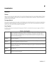
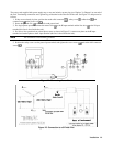
The Table A-2 in Appendix A gives the dimensions of your power supply. The cabinet has plastic feet that are shaped to
ensure self-alignment when stacked with other Agilent System II cabinets. The feet may be removed for rack mounting.
Your power supply must be installed in a location that allows sufficient space at the sides and rear of the cabinet for
adequate air circulation. Minimum clearances are 1 inch (25 mm) along the sides. Do not block the fan exhaust at the rear of
the unit.
Rack Mounting
The power supply can be mounted in a standard l9-inch rack panel or cabinet. Rack mounting kits are available as Option
908 or 909 (with handles). Installation instructions are included with each rack mounting kit.
This power supply requires instrument support rails for non-stationary installations. These are
normally ordered with the cabinet and are not included with the rack mounting kits.
Temperature Performance
A variable-speed fan cools the unit by drawing air through the sides and exhausting it out the back. Using Agilent rack
mount or slides will not impede the flow of air. The temperature performance is as follows:
The unit operates without loss of performance within the temperature range of 0 °C to 45 °C.
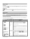
Input Power Source
Do not apply power to the power supply until directed to do so in Chapter 3.
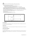
Check the line label on the rear of your unit and verify that the voltage shown there
corresponds to the nominal line voltage of your power source. If it does not, see Appendix E - "Line
Voltage Conversion" for instructions on changing the power supply's line voltage configuration.
Note This product requires single-phase input voltage.
You can operate your unit from a nominal 200 V or a 230 V single-phase power source, or from the line-to-line voltage of a
208-volt, 3-phase source. The proper source is indicated on the rear
label ( , Figure 2-2). See "AC Input
Ratings" in Table A-2 for the voltage and frequency range for each type of power source.
Note The power source must be a dedicated line with no other devices drawing current from it.
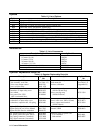
The line fuse is located inside the power supply. Table 1-4 identifies the replacement fuse. See "In Case of Trouble" in
Chapter 3 for instructions on fuse replacement.
Installing the Power Cord
Installation of the power cord must be done by a qualified electrician and in accordance with local
electrical codes.