


@@2:/96;4B@A9/<D.;1B@A.4
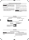
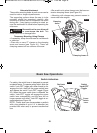
The dust collection system used on this tool is
unique because it is not attached to the upper
guard. This placement provides superior dust col-
lection for the majority of cuts.
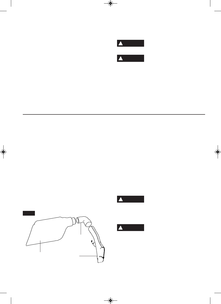
9/<D
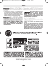
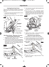
The CM12 offers two dust chute configurations, ei-
ther with or without the dust elbow.
Use the dust elbow when working in tight locations
or up against a wall where space is limited behind
the saw. For optimal dust collection, set the dust
elbow aside and connect the dust bag directly to
the dust chute.
To attach the dust elbow, slide the elbow onto the
dust chute for a pressure fit (Fig. 7).
Direct the elbow in any direction preferred based
on your tool setup and location.
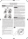
AA.05B@A.4
To attach the dust bag, slide the bag onto the dust
chute or the elbow for a pressure fit. (See Figure 7)
92.;6;4B@A.4
After the dust bag is 2/3 to 3/4 full, remove it form
the saw. Bring the bag to a proper container and
pull open the zipper located on the bottom of the
bag. Hold the bag by the coupler end and shake it
vigorously until all the dust and debris fall from it.
Close zipper and reattach the bag to the saw.
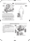
22EA?2:29F0.?23B9D52;16@
=<@6;4<31B@A<;<AA5?<D
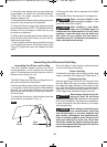
@.D1B@A<;.;<=2;36?2Materials in fine particle
form may be explosive. Spontaneous combustion,
in time, may result from the mixture of oil or water
with dust particles.
*52;@.D6;4052:60.99F=?2@
@B?2A?2.A219B:/2?=.6;AA5.A
:.F/292.1/.@21<?.;F<A52?:.A2?6.9@A5.A
:.F0<;A.6;0.?06;<42;@B@2@=206.9=?20.B
A6<;@@B6A./92?2@=6?.A<?:B@A/2D<?;/F.99
=2?@<;;292;A2?6;4A52D<?8.?2.*<?8.?2.
@5<B91/2@2.921/F=9.@A60@522A6;4.;1=2?
@<;@;<A=?<A20A21@5<B91/282=A<BAB;A69D<?8
.?2.6@A5<?<B459F092.;21
@@2:/96;4B@A9/<D;1B@A.4
-12-
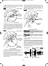
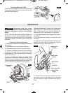
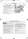
3. Place the outer washer over the arbor shaft and
finger-tighten the blade bolt (counterclockwise).
Check that the blade remained on the inner
washer’s support ring.
4. Rotate the blade slowly while pressing the arbor
lock until it fully seats into its lock position.
5. Using the 6/4mm hex key, firmly tighten the blade
bolt counterclockwise. NOTE: This bolt has lefthand
threads. Do not over tighten. A 6mm hex key may
be used as an alternate.
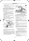
6. Slowly rotate the upper guard down and the cover
plate will also rotate until it seats on top of the for-
ward cover plate screw.
7. Once in place, rotate the upper guard back up and
it will expose the forward cover plate screw. (See
Figure 3) Tighten the screw and release the lower
guard
8. Be sure the arbor lock is released so the blade
turns freely.
9. Place the 6/4mm hex key back in storage area.
"2C2? B@2 @.D D6A5<BA 0<C2?
=9.A2@20B?29F6; =9.02Lower
guard will not function properly.
3A2? 6;@A.996;4 . ;2D /9.12
:.82@B?2A52/9.121<2@;<A
6;A2?32?2D6A5A52A./926;@2?A.AH.;1H/2C29
=<@6A6<;@ <D2?A52/9.126;A<A52/9.12@9<A
.;1 05208 3<? .;F 0<;A.0A D6A5 A52 /.@2 <?
AB?;A./92@A?B0AB?23A52/9.120<;A.0A@/.@2<?
A./92@228.BA5<?6G21@2?C602
!
WARNING
!
WARNING
FIG. 7
!
WARNING
!
WARNING
B@A
5BA2
B@A
5BA2
9/<D
BM 2610021316 10-11 E:BM 2610021316 10-11 E.qxp 10/17/11 11:02 AM Page 12