


-7-
• Connect this saw to a 120V, 15-amp branch circuit
with a 15-amp fuse or circuit breaker. Using the
wrong size fuse can damage the motor.
• Fuses may “blow” or circuit breakers may trip fre-
quently if motor is overloaded. Overloading can
occur if you feed the blade into the workpiece too
rapidly or start and stop too often in a short time.
• Most motor troubles may be traced to loose or in-
correct connections, overload, low voltage (such
as small size wire in the supply circuit or too overly
long supply circuit wire). Always check the con-
nections, the load and the supply circuit whenever
motor does not work well.
920A?60?.82
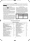
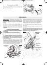
Your saw is equipped with an automatic electric
brake which is designed to stop the blade from spin-
ning in about five (5) seconds after you release the
trigger switch.
*52;2920A?60.9=<D2?6@9<@A1B2
A</9<D;3B@2<?<A52?0.B@2@
A52:<A<?D6994?.1B.99F@9<D1<D;'52/?.86;4
.0A6<;6@6;6A6.A21#" ,/FA52?292.@2<3A52
A?6442?@D6A05
The electric blade brake of your miter saw has been
designed for highest degree of reliability, but unex-
pected circumstances such as contamination on the
commutator and brushes or failure of motor’s com-
ponents can cause the brake not to activate. If this
condition occurs, turn the saw “ON” and “OFF” four
to five times without contacting the workpiece. If the
tool operates but the brake does not consistently
stop the blade in about five (5) seconds, DO NOT
use saw and have it serviced immediately.
'52/?.82.0A6<;<3A56@@.D6@
;<A6;A2;121.@.@.32AF32.AB?2
%2:2:/2?A<92AA52@.D/9.120<:2A<.0<:
=92A2@A<= /23<?2 ?.6@6;4 A52 /9.12 3?<: A52
D<?8=6202@.9D.F@A524B.?1@F@A2:6@F<B?
/2@A=?<A20A6<;.4.6;@AB;6;A2;A6<;.90<;A.0A
D6A5.@=6;;6;4@.D/9.12")%D2142<=2;
<?1232.AA5209<@6;4.0A6<;<3A529<D2?4B.?1
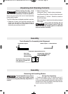
920A?60.9%2>B6?2:2;A@
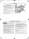
2AA6;4'<;<D,<B?!6A2?&.D&22=.42
'<.C<616;7B?F3?<:.00612;A.9
@A.?A6;4?2:<C2=9B43?<:=<D2?
@<B?02<BA92A/23<?2:.86;4.;F.17B@A:2;A@
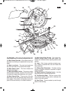
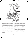
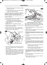
%2.?#;25.;121.??F.;192 – This handle
is positioned for optimal one-handed carrying.
'<=.??F.;192 – This handle is built into the
head assembly for transportation.
&D6A05 <08#'<4492 – The toggle needs to
be moved left or right before the power switch can
be pressed.
$<D2?&D6A05 – The power switch used with the
Lock-OFF Toggle energizes the unit.
&D6A05.;192– The power switch used with the
ambidextrous toggle energizes the saw.
<D2?9.12B.?1 <D2?9.12B.?1 6= –
The lower blade guard helps protect your hands
from the spinning blade. It retracts as the blade is
lowered. Lip can be used to raise the lower guard
when guard becomes jammed on a workpiece.
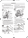
9.12 – Use only 12” (305 mm) blades with 1”
(25.4 mm) arbor hole.
9.12*?2;05&A<?.42 – Used in blade change
process; tightening and loosening blade and blade
guard.
56=23920A<?– This protects against large chips
from entering the upper guard.
(==2?9.12B.?1 – Covers upper portion of
the blade.
&9616;42;02 – Supports the workpiece and
features cast-in scales for repetitive cuts and holes
to secure an auxiliary fence. Slide left side out prior
to beveling head left. Right side is stationary.
&A.A6<;.?F2;02 – Stationary fence is bolted
to the base and will support the workpiece when the
sliding fence is removed. (Note the right side does
not slide or remove.)
!
WARNING
!
WARNING
!
WARNING
Cutting Crown Molding . . . . . . . . . . . . . . . .26-32
Special Cuts . . . . . . . . . . . . . . . . . . . . . . . .32
!.6;A2;.;02.;1 B/?60.A6<; . . . . . . . . .33-34
'?<B/92@5<<A6;4 . . . . . . . . . . . . . . . . . . . .35-36
002@@<?62@ . . . . . . . . . . . . . . . . . . . . . . .37
BM 2610021316 10-11 E:BM 2610021316 10-11 E.qxp 10/17/11 11:02 AM Page 7