


-21-
17B@A6;4&9616;42;02 <08 2C2?
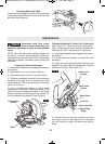
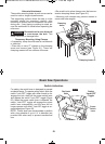
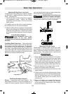
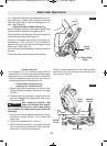
To tighten lock: If the sliding fence does not operate
as described, it needs adjustment. Remove sliding
fence – (see page 20).
1. Push firmly down on the locking block to expose
the adjustment screw – Using a #2 Phillips
screwdriver, turn the screw 1/12 turn to the next
notch in block.
A: To tighten lock: turn the screw counter-clockwise.
B: To loosen lock: turn the screw clockwise.
2. Replace sliding fence by putting its large square
hole over the locking block. Slide fence fully in and
close the cover plate tab. It should move freely
and be locked tightly anywhere along its range of
travel.
<;4*<?8=6202&B==<?A
<;4 D<?8=6202@ 5.C2 . A2;
12;0F A< A6= <C2? B;92@@
09.:=211<D;.;1=?<=2?9F@B==<?A213?<:B;
12?;2.A5
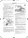
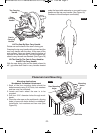
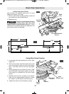
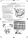
#=2?.A6;4.@2EA2;@6<;@– These extensions
provide extra workpiece support and are especially
useful when cutting long workpieces. To reposition
the extensions, simply unlock the base extension
lock levers, reposition the extensions and lock the
levers (see Figure 28). The right extension lock lever
tightens by rotating clockwise and the left lock lever
tightens by rotating counterclockwise.
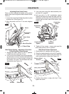
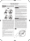
116A6<;.9*<?8=6202&B==<?A
9<08@ – Long pieces need extra support. The
base height is 4 inches. Cut two 2x4 pieces to 4" in
length and fasten together. Boards of these thick-
ness and height can be used to create auxiliary sup-
port extensions for long workpieces.
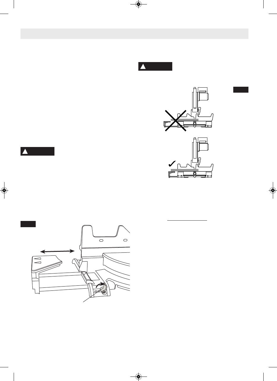
9D.F@.17B@AA52@9616;4/.@2
2EA2;@6<;A<@B==<?AD<?8=6202
Unsupported workpiece can move out of position
during cut and cause injury and/or tol damage.
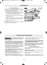
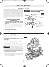
BE696.?F2;02
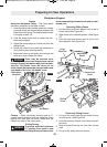
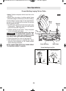
!.86;4.;BE696.?F2;02
Certain types of molding need a fence face exten-
sion because of the size and position of the work-
piece. Holes are provided in the fence to attach an
auxiliary fence. The auxiliary fence is used with the
saw in the 0° bevel position only
.
'<3.@A2;3?<:3?<;A
1. Place a piece of wood a minimum of 1/2" thick x
5-1/2" tall against the miter saw fence (see Figure
30). The right side should be only 2-3/4" tall to
avoid motor interference during miter rotating.
Check that auxiliary fence assembly does not in-
terfere with head assembly. (See Figure 30 & 31).
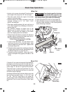
2. Mark the locations of the support holes on the
wood from the back side of the fence.
3. Drill and countersink the holes on the front of the
support board.
4. Fasten from front of fence: Attach (each) auxiiary
fence using two (2) 3/16" flat head machine bolts.
With 3/4" auxiliary fence, use 1-1/2" long bolts Se-
cure behind metal fence with washer and #5
machine nuts.
5. Make a full depth cut to create the blade slot.
Check for interference between the auxiliary
fence and the lower blade guard. Make adjust-
ments as necessary.
!
WARNING
<08 2C2?
FIG. 28
!
WARNING
.@60&.D#=2?.A6<;@
FIG. 29
BM 2610021316 10-11 E:BM 2610021316 10-11 E.qxp 10/17/11 11:02 AM Page 21