


-24-
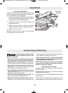
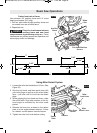
•A miter cut is a cross-cut made at 0° bevel and any
miter angle in the range from 52° left and right.
• The miter scale shows the angle of the blade
relative to the fence angle.
• Positive detents have been provided for fast and
accurate mitering at 0°, 15°, 22.5°, 31.6°
and 45° left and right.
• The crown molding detents (left and right) are at
31.6° (See Cutting Crown Molding for more infor-
mation page 28).
• For precision settings at angles next to the
detents, use the detent override to lock out the
detent. This prevents the wedge on the detent
lever from slipping back into the detent.
• The kerf inserts should be as close to the blade as
possible without touching the blade (see Kerf In-
serts for adjustment procedures).
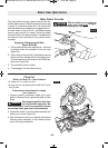
<99<DA52@26;@A?B0A6<;@3<?:.86;4
F<B?:6A2?0BA
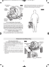
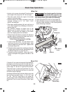
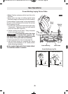
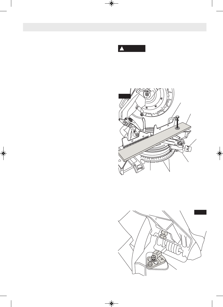
1. Loosen miter lock knob. Lift miter detent lever
and move the saw to the desired angle, using
either the detents or the miter scale. Tighten miter
lock knob (Figure 35).
2. Extend the base extensions and fence on the side
on which the cut will be made. (See Sliding Fence
and Base Extension on page 20 & 21).
3. Properly position workpiece. Make sure work-
piece is clamped firmly against the table or the
fence.
(@209.:=6;4=<@6A6<;A5.A1<2@
;<A6;A2?32?2D6A5<=2?.A6<;2
3<?2@D6A056;4<;9<D2?52.1.@@2:/9FA<:.82
@B?209.:=092.?@4B.?1.;152.1.@@2:/9F
4. Follow procedures for chop cut (see page 23).
5. Wait until blade comes to a complete stop before
returning head assembly to the raised position
and/or removing workpiece.
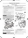
!6A2?BA
!
WARNING
!.A2?6.9
9.:=
*<?8=6202
!6A2?
&0.92
!6A2?
<08
;</
2A2;A@
2C29BA
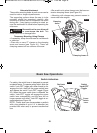
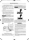
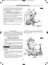
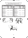
A “bevel cut” is a cross-cut made with the blade per-
pendicular to the fence and with the table set at 0°
miter. The blade can be tilted at any angle within the
saw’s range: 47° left and -2° right from the vertical.
The bevel scale is sized and positioned for easy
reading. And the side bevel lock lever is to lock and
unlock the various settings.
A rotating Left Bevel Stop indicator allows you to set
the most common bevel stops – 0°, 33.9°, 45° and
47° Left. The 33.9° bevel stop is for cutting 38°
“spring angle” crown molding flat on the table. (See
Compound Cuts for more information.) (See Figure
36)
H 23A
2C29&A<=
FIG. 35
FIG. 36
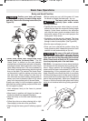
.@60&.D#=2?.A6<;@
!6A2?2A2;A
2C2?
BM 2610021316 10-11 E:BM 2610021316 10-11 E.qxp 10/17/11 11:02 AM Page 24