


-6-
“READ ALL INSTRUCTIONS” — Failure to follow the SAFETY RULES identified by
BULLET (•) symbol listed BELOW and other safety precautions, may result in serious
personal injury.
!
WARNING
&.32AF
<B/92;@B9.A21'<<9@
Double insulation is a design concept used in
electric power tools which eliminates the need for
the three wire grounded power cord and grounded
power supply system. It is a recognized and ap-
proved system by Underwriter’s Laboratories, CSA
and Federal OSHA authorities.
• Servicing of a tool with double insulation requires
care and knowledge of the system and should be
performed only by a qualified service technician.
• WHEN SERVICING, USE ONLY IDENTICAL RE-
PLACEMENT PARTS.
• POLARIZED PLUGS. To reduce the risk of elec-
trical shock, your tool is equipped with a polarized
plug (one blade is wider than the other), this plug
will fit in a polarized outlet only one way. If the plug
does not fit fully in the outlet, reverse the plug. If it
still does not fit, contact a qualified electrician to in-
stall the proper outlet. To reduce the risk of electri-
cal shock, do not change the plug in any way.
EA2;@6<;<?1@
• Replace damaged cords immediately. Use of
damaged cords can shock, burn or electrocute.
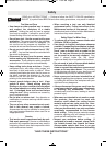
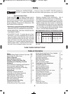
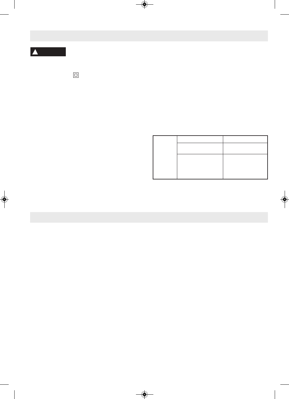
• If an extension cord is necessary, a cord with ade-
quate size conductors should be used to prevent ex-
cessive voltage drop, loss of power or overheating.
The table shows the correct size to use, depending
on cord length and nameplate amperage rating of
tool. If in doubt, use the next heavier gauge. Always
use U.L. and CSA listed extension cords.
%#!!"&-&#+'"&#"#%&
"#' The smaller the gauge number, the heavier
the cord.
'<<9P@
:=2?2
%.A6;4
<?1&6G26;*
*6?2&6G2@6;::
3-6
6-8
8-10
10-12
12-16
18 16 16 14 0.75 0.75 1.5 2.5
18 16 14 12 0.75 1.0 2.5 4.0
18 16 14 12 0.75 1.0 2.5 4.0
16 16 14 12 1.0 2.5 4.0 —
14 12 — — — — — —
25 50 100 150 15 30 60 120
<?1 2;4A56;22A <?1 2;4A56;!2A2?@
'./92<3<;A2;A@
&.32AF . . . . . . . . . . . . . . . . . . . . . . . . . . . . . .2-6
General Safety Rules For Bench Top Tools .2-3
Safety Rules For Miter Saws . . . . . . . . . . . .3-5
'./92<3<;A2;A@ . . . . . . . . . . . . . . . . . . . .6
920A?60.9%2>B6?2:2;A@ . . . . . . . . . . . . . . .7
2AA6;4'<;<D,<B?!6A2?&.D . . . . . . .7-9
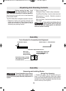
(;=.086;4.;152086;4<;A2;A@ . . . . .10
@@2:/9F . . . . . . . . . . . . . . . . . . . . . . . . . . .10-13
Tools Needed for Assembly and Alignment .10
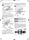
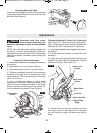
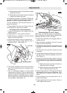
Removing and installing Blades . . . . . . . . . .10-12
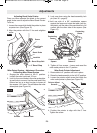
Assembling Dust Elbow and Dust Bag . . . . .12
Attaching Miter Lock Knob . . . . . . . . . . . . . .13
17B@A:2;A@ . . . . . . . . . . . . . . . . . . . . . . . . .13-16
Checking 0° Bevel Adjustment . . . . . . . . . . .13
Checking Left 45° Bevel Adjustment . . . . . . .14
Adjusting Bevel Scale Pointer . . . . . . . . . . . .15
Calibrating Miter Detent System . . . . . . . . . .15
Miter Scale Pointer Adjustment . . . . . . . . . . .15
Kerf Insert Adjustment . . . . . . . . . . . . . . . . . .16
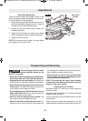
'?.;@=<?A6;4.;1!<B;A6;4 . . . . . . . . . . .16-17
Preparing to Lift the Saw . . . . . . . . . . . . . . . .16
Lift the Saw by Rear Carry Handle . . . . . . . .17
Lift the Saw by the Cast-In Carry Handles . .17
$9.02:2;A.;1!<B;A6;4 . . . . . . . . . . . . .17-18
Workbench Permanent Attachment . . . . . .17
Alternate Attachment . . . . . . . . . . . . . . . . .18
.@60&.D#=2?.A6<;@ . . . . . . . . . . . . . . .18-19
Switch Activation . . . . . . . . . . . . . . . . . . . .18
Body and Hand Position . . . . . . . . . . . . . . .19
$?2=.?6;43<?&.D#=2?.A6<;@ . . . . . . . .20
Workpiece Support . . . . . . . . . . . . . . . . . . .20
Operating Sliding Fence . . . . . . . . . . . . . . .20
Removing Sliding Fence . . . . . . . . . . . . . .20
.@60&.D#=2?.A6<;@ . . . . . . . . . . . . . . .21-25
Adjusting Sliding Fence Lock Lever . . . . . .21
Long Workpiece Support . . . . . . . . . . . . . .21
Additional Workpiece Support . . . . . . . . . .21
Using Miter Detent System . . . . . . . . . . . .22
Miter Detent Override . . . . . . . . . . . . . . . . .23
Chop Cut . . . . . . . . . . . . . . . . . . . . . . . . . .23
Miter Cut . . . . . . . . . . . . . . . . . . . . . . . . . . .24
Bevel Cut . . . . . . . . . . . . . . . . . . . . . . . . . .24
Compound Cuts . . . . . . . . . . . . . . . . . . . . .25
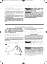
Cutting Base Molding . . . . . . . . . . . . . . . . .26
M&)'&"&'%('#"&N
BM 2610021316 10-11 E:BM 2610021316 10-11 E.qxp 10/17/11 11:02 AM Page 6